ENGINE PERFORMANCE
3.0L SC
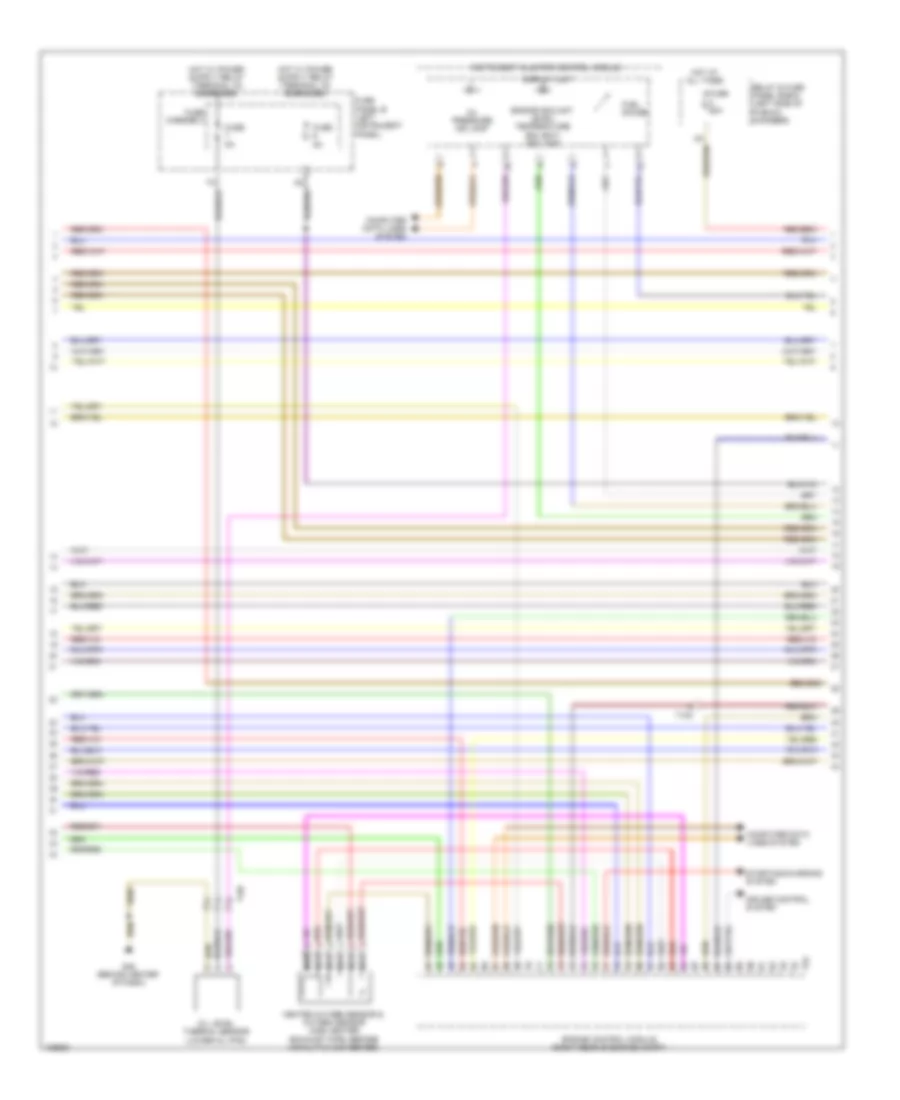
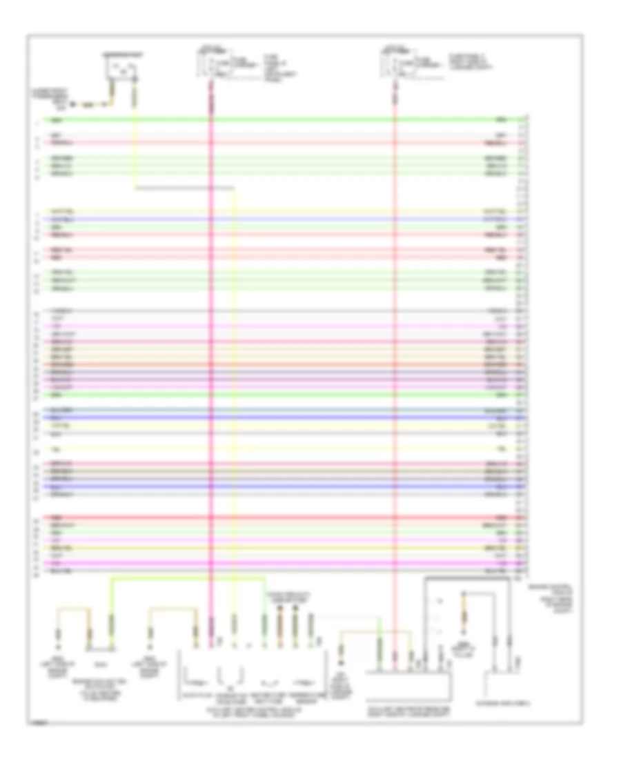
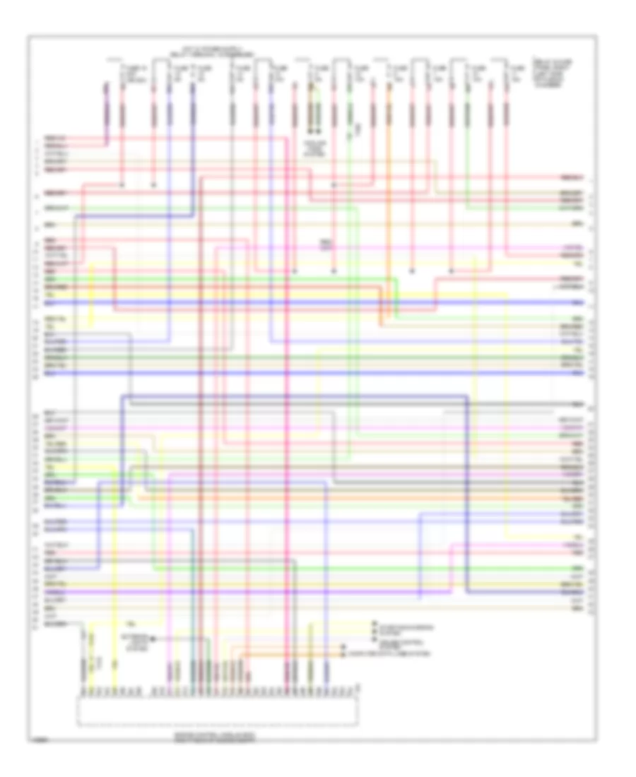
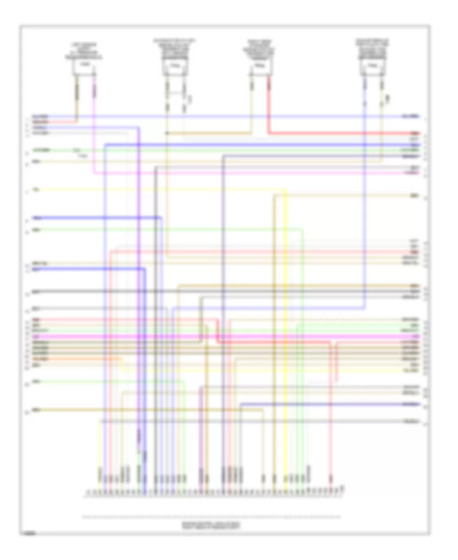
3.0L SC, Engine Performance Wiring Diagram (1 of 7) for Audi Q7 Prestige S 2013

List of elements for 3.0L SC, Engine Performance Wiring Diagram (1 of 7) for Audi Q7 Prestige S 2013:
- (right side of plenum chamber) g609
- 10a
- 13a
- 14a
- 15a
- 17a
- Accelerator pedal position (app) sensor 1 & 2
- Anti-theft system
- Backup & multi-transmission transmission range switch
- Cooling fans system
- Engine control module (right rear of engine compt)
- Fuse 10a
- Fuse 150a
- Fuse 15a
- Fuse 20a
- Fuse 5a
- Fuse panel d (below driver seat)
- Heated oxygen sensor (ho2s) 2 & oxygen sensor (o2s) heater 2 (exhaust pipe, before catalytic converter)
- Hot at all times
- Nca
- Oxygen sensor (02s) 2 after three way catalytic (twc) converter & heater for oxygen sensor 2 after catalytic converter
- Oxygen sensor (o2s) after three way catalytic (twc) converter & heater for oxygen sensor 1 after catalytic converter
- Red
- Relay & fuse panel e-box (left side of plenum chamber)
- Starting/charging system
- T10c
- T10e
- T10m
- T14h
- T17d
- T6k
- T94
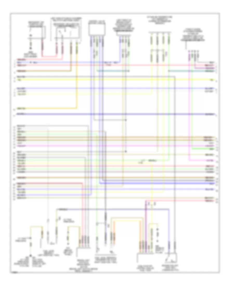
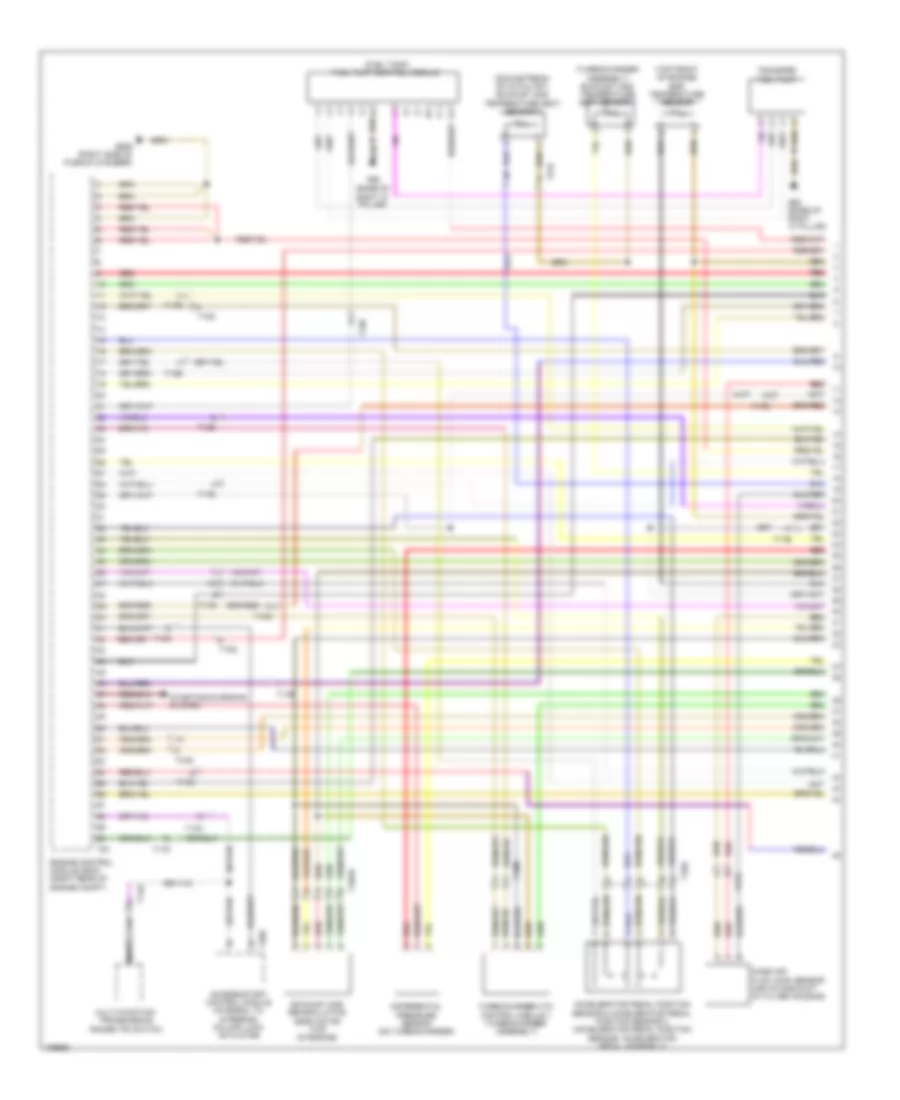
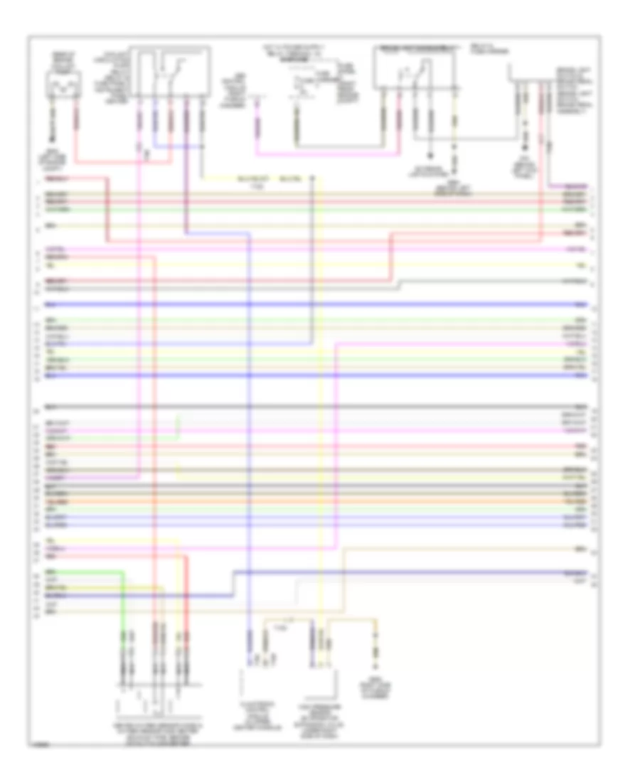
3.0L SC, Engine Performance Wiring Diagram (2 of 7) for Audi Q7 Prestige S 2013
List of elements for 3.0L SC, Engine Performance Wiring Diagram (2 of 7) for Audi Q7 Prestige S 2013:
- (left engine compt) oil pressure regulation valve
- (left side of plenum chamber) relay & fuse panel e-box
- (rear of right cylinder head)
- (right cylinder head, in high pressure pump) fuel metering valve
- (w/ fuel system diagnostic pump) leak detection pump (ldp)
- Brake light disable relay
- Camshaft adjustment valve 1
- Camshaft adjustment valve 2 (rear of left cylinder head)
- Charge air cooling pump
- Climatronic control module (in upper center console)
- Evaporative emission (evap) canister purge regulator valve
- G609 (right side of plenum chamber)
- G664 (behind left side of dash)
- G671 (left front long member)
- High pressure sensor (evaporator expansion valve, under right side of dash)
- Intake manifold runner control (imrc) valve
- Red
- Relay & fuse carrier (center instrument panel)
- Secondary air injection (air) solenoid valve
- T10d
- T10e
- T10m
- T14l
- T16d
- T17d
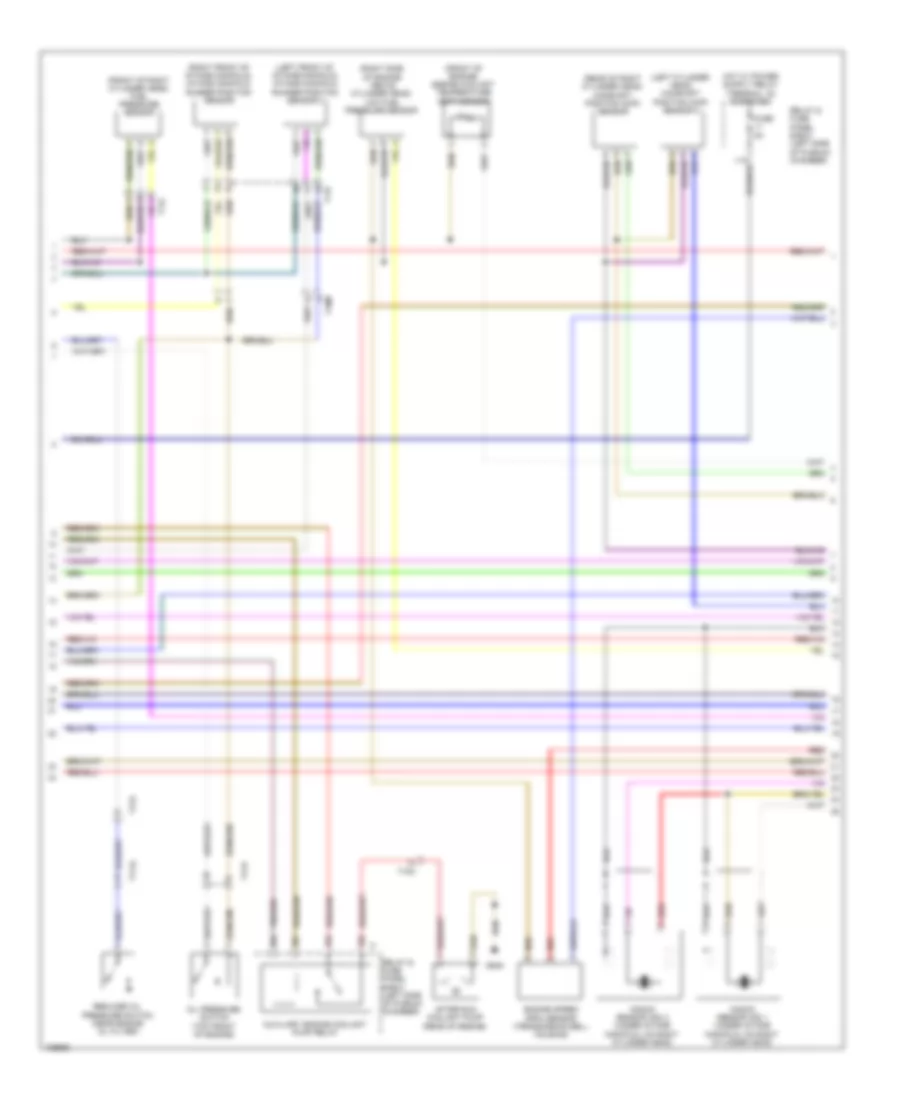
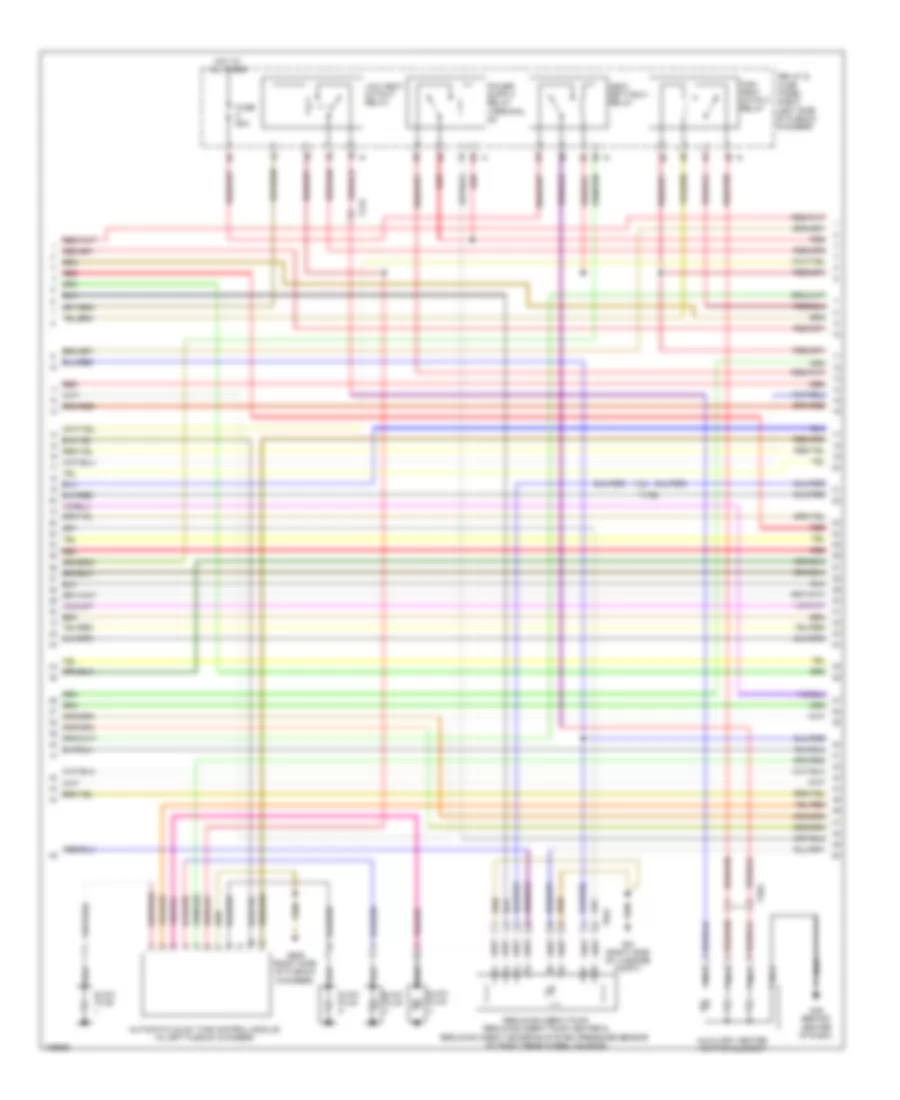
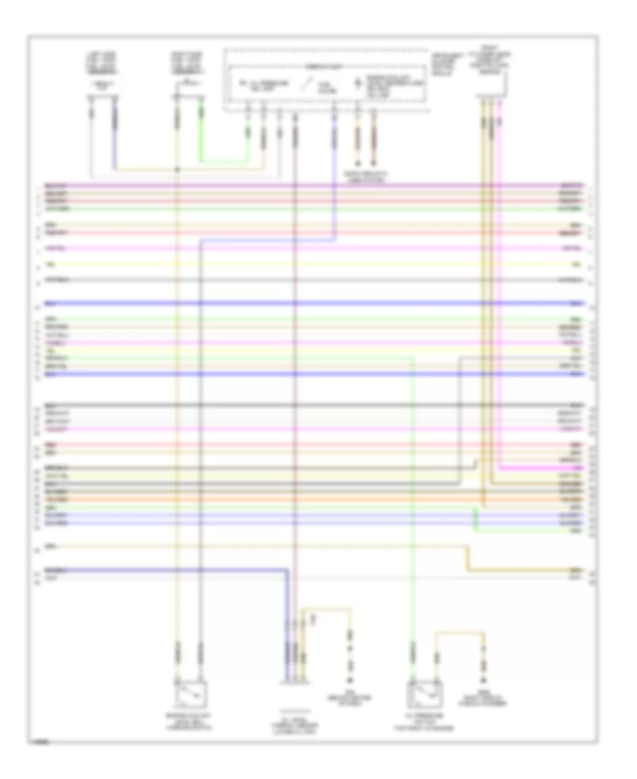
3.0L SC, Engine Performance Wiring Diagram (3 of 7) for Audi Q7 Prestige S 2013
List of elements for 3.0L SC, Engine Performance Wiring Diagram (3 of 7) for Audi Q7 Prestige S 2013:
- Computer data lines system
- Cruise control system
- Display unit
- Engine control module (right rear of engine compt)
- Engine coolant level/ temperature (ecl/ect) ind lamp
- Fuel gauge
- Fuse 50a
- Fuse 5a
- Fuse carrier 3
- Fuse panel b (left instrument panel)
- G45 (behind center of dash)
- Heated oxygen sensor & oxygen sensor (o2s) heater (exhaust pipe, before catalytic converter)
- Hot at all times
- Instrument cluster control module
- Nca
- Oil level thermal sensor (lower oil pan)
- Oil pressure ind lamp
- Red
- Relay & fuse panel e-box (left side of plenum chamber)
- Starting/charging system
- T10c
- T10f
- T94
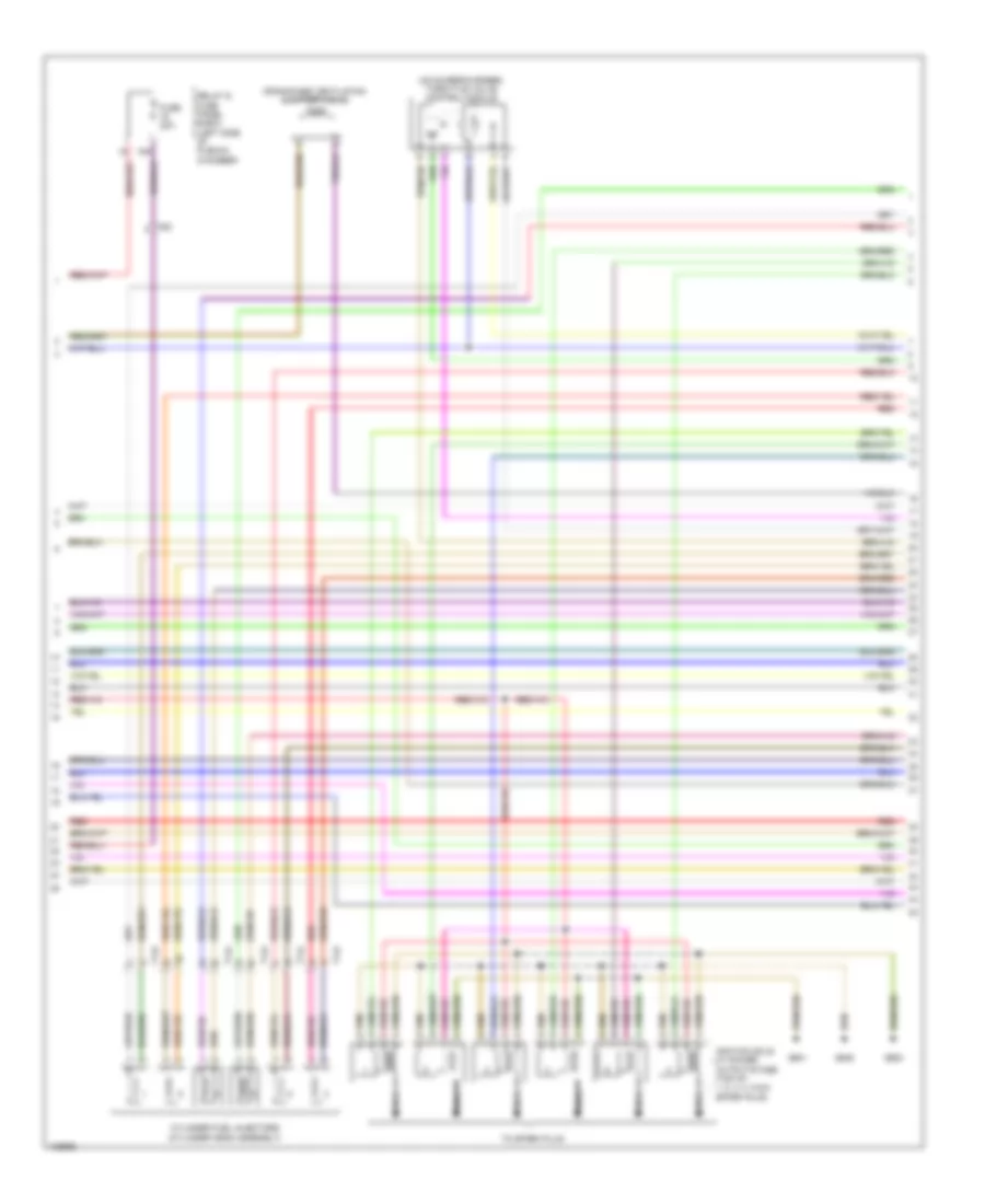
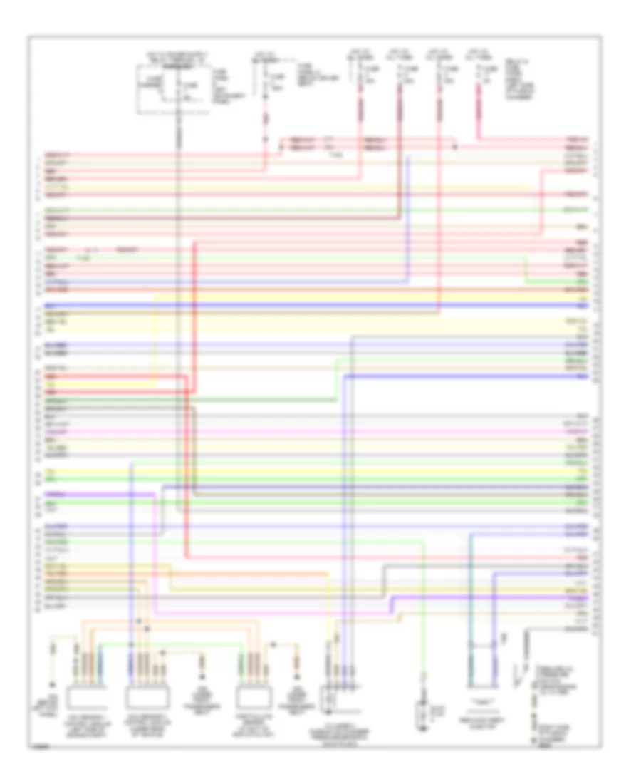
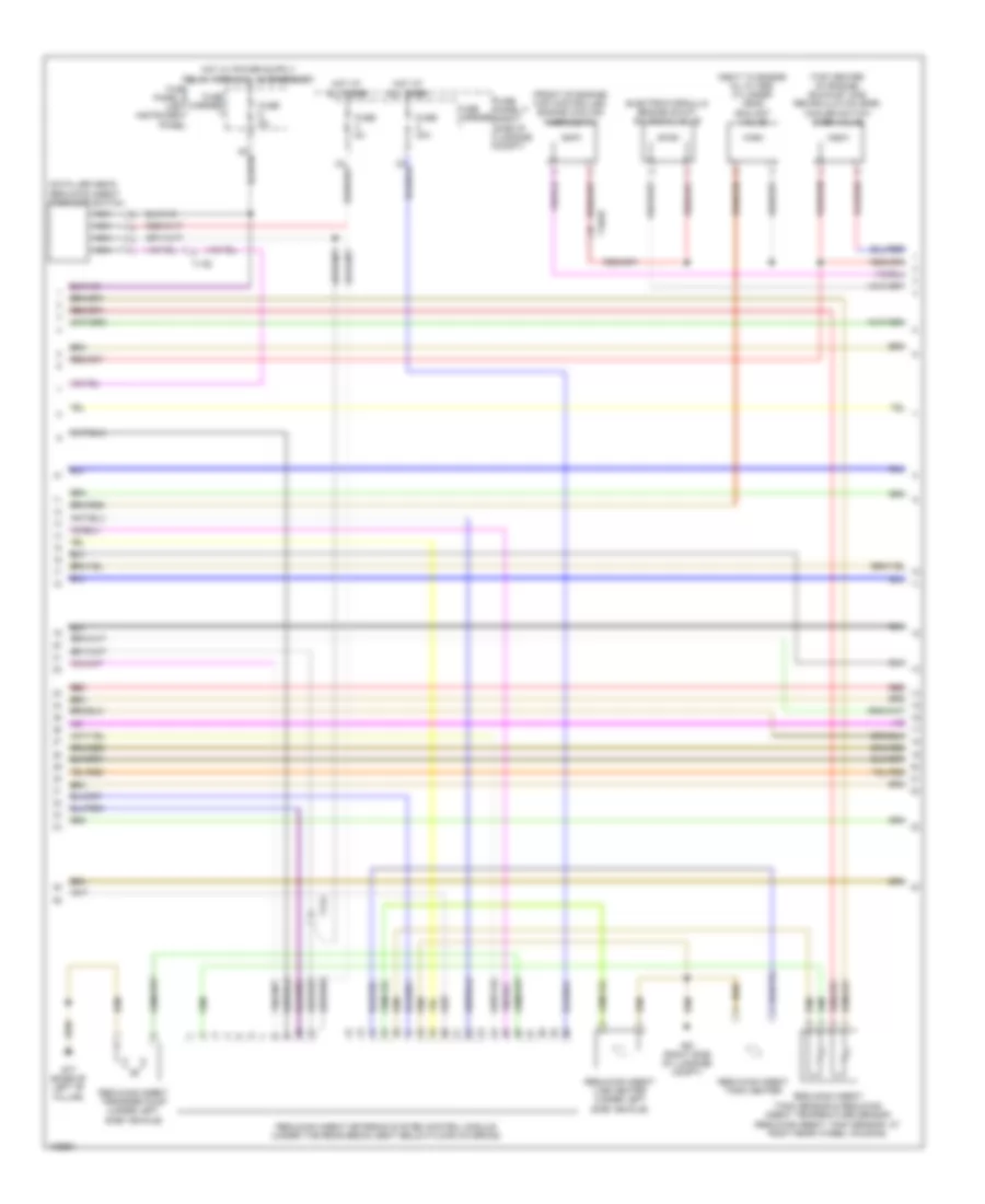
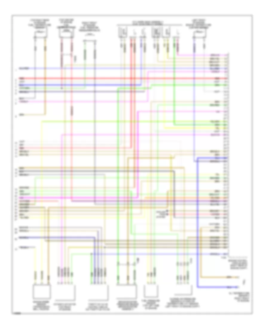
3.0L SC, Engine Performance Wiring Diagram (4 of 7) for Audi Q7 Prestige S 2013
List of elements for 3.0L SC, Engine Performance Wiring Diagram (4 of 7) for Audi Q7 Prestige S 2013:
- (left front of engine compt) intake manifold temperature sensor & charge air pressure sensor
- (left side of plenum chamber) relay & fuse panel e-box
- (throttle end of supercharger)
- Brake light switch & brake pedal switch (brake light switch: brake pedal assembly)
- Control valve control module
- Engine coolant level (ecl) warning switch
- Fuel level sensor & transfer fuel pump (right side fuel tank)
- Fuel level sensor 2 (left side fuel tank)
- Fuel pump (fp) control module (fuel tank)
- G44 (behind left kick panel)
- G61 (w/o tank prewiring) (base of left 'c' pillar)
- G62 (base of right "c" pillar)
- G62 (w/ tank prewiring) (base of right 'c' pillar)
- G685 (right front long member)
- Intake air temperature (iat) & manifold absolute pressure (map) sensor
- Intake air temperature (iat) sensor 2 & charge air pressure sensor 2
- Secondary air injection (air) pump motor
- Secondary air injection (air) pump relay
- T17d
- T2k
- T5k
- W/ tank prewiring
3.0L SC, Engine Performance Wiring Diagram (5 of 7) for Audi Q7 Prestige S 2013
List of elements for 3.0L SC, Engine Performance Wiring Diagram (5 of 7) for Audi Q7 Prestige S 2013:
- (front of engine) engine coolant temperature (ect) sensor
- (front of right cylinder head) fuel pressure sensor
- (left cylinder head) camshaft position (cmp) sensor 2
- (left front of intake manifold) intake manifold runner position sensor 2
- (rear of right cylinder head) camshaft position (cmp) sensor
- (right front of intake manifold) intake manifold runner position sensor
- (right side of engine above cylinder head) low fuel pressure sensor
- 19a
- 19c
- 19d
- 19e
- After run coolant pump (rear of engine)
- Auxiliary engine coolant pump relay
- Engine speed (rpm) sensor (transmission bell housing)
- Fuse 5a
- G645
- Knock sensor (ks) 1 (under intake manifold, on right cylinder head)
- Knock sensor (ks) 2 (under intake manifold, on right cylinder head)
- Oil pressure switch (top front of engine)
- Red
- Reduced oil pressure switch (near engine oil filter)
- Relay & fuse panel e-box (left side of plenum chamber)
- T10m
- T114l
- T14f
- T14l
- T17d
3.0L SC, Engine Performance Wiring Diagram (6 of 7) for Audi Q7 Prestige S 2013
List of elements for 3.0L SC, Engine Performance Wiring Diagram (6 of 7) for Audi Q7 Prestige S 2013:
- (on supercharger) throttle valve control module
- 16a
- Crankcase ventilation shut-off valve
- Cylinder fuel injectors (cylinder head assembly)
- Fuse 20a
- G600
- G601
- G645
- Ignition coils w/ power output stage (top of 1, 2, 3, 4, 5 & 6 spark plug)
- Nca
- Red
- Relay & fuse panel e-box (left side of plenum chamber)
- T14f
- T14l
- T6k
- To spark plug
3.0L SC, Engine Performance Wiring Diagram (7 of 7) for Audi Q7 Prestige S 2013
List of elements for 3.0L SC, Engine Performance Wiring Diagram (7 of 7) for Audi Q7 Prestige S 2013:
- (right rear of engine compt)
- (under front passenger's seat)
- Air blower
- Antenna amplifier 2
- Auxiliary heater control module (in left front wheel housing)
- Auxiliary heater rf receiver (right side of luggage compt)
- Combustion
- Computer data lines system
- Engine control module
- Engine coolant (ec) switch-off valve (heater) (if equipped)
- Fuse 20a
- Fuse 5a
- Fuse carrier 1
- Fuse panel b (left instrument panel)
- Fuse panel f (right side of luggage compt)
- G35
- G51 (right side of luggage compt)
- G640 (left side of engine compt)
- G669 (right "d" pillar)
- Glow plug
- Heat fuse
- Heater over
- Hot at all times
- Metering pump
- Nca
- Red
- Sensor
- T2b
- T2bq
- T2p
- T60
- T6b
- T6u
- Temperature
3.0L TURBO DIESEL
3.0L Turbo Diesel, Engine Performance Wiring Diagram (1 of 9) for Audi Q7 Prestige S 2013
List of elements for 3.0L Turbo Diesel, Engine Performance Wiring Diagram (1 of 9) for Audi Q7 Prestige S 2013:
- (base of
- (downstream of catalyst) exhaust gas temperature (egt) sensor 3
- (fuel tank) fuel pump control module
- (top front of engine) egr temperature sensor
- (turbocharger assembly) exhaust gas temperature (egt) sensor 1
- Accelerator pedal position sensor & accelerator pedal position sensor 2 (accelerator pedal position sensor: accelerator pedal assembly)
- Access/start control module (integral to steering column lock actuator)
- Differential pressure sensor (on turbocharger)
- Engine control module (ecm) (right rear of engine compt)
- Exhaust gas recirculation (egr) motor (top of engine)
- G609 (right side of plenum chamber)
- G62
- G62 (base of right "c" pillar)
- Mass air flow (maf) sensor (air intake duct at filter housing)
- Multi-function transmission range (tr) switch
- Nca
- Red
- Right "c" pillar)
- Starting/charging system
- T10ab
- T10b
- T10c
- T10d
- T10e
- T10m
- T14h
- T17d
- T17e
- T20e
- T91
- Transfer fuel pump
- Turbocharger (tc) control module 1 (turbocharger assembly)
3.0L Turbo Diesel, Engine Performance Wiring Diagram (2 of 9) for Audi Q7 Prestige S 2013
List of elements for 3.0L Turbo Diesel, Engine Performance Wiring Diagram (2 of 9) for Audi Q7 Prestige S 2013:
- Automatic glow time control module (in left plenum chamber)
- Auxiliary heater heating element
- Fuse 60a
- G45 (behind center of dash)
- G51 (right side of luggage compt)
- G609 (right side of plenum chamber)
- Glow plug
- Heat setting 3 relay
- High heat output relay
- Hot at all times
- Low heat output relay
- Nca
- Red
- Reducing agent pump, reducing agent pump heater & reducing agent metering system pressure sensor (at right rear wheel housing)
- Relay & fuse panel e-box (left side of plenum chamber)
- T17e
- T2bg
- T8al
3.0L Turbo Diesel, Engine Performance Wiring Diagram (3 of 9) for Audi Q7 Prestige S 2013
List of elements for 3.0L Turbo Diesel, Engine Performance Wiring Diagram (3 of 9) for Audi Q7 Prestige S 2013:
- (right side of plenum chamber) g609
- 17a
- Cylinder 2 combustion chamber pressure sensor & glow plug 2
- Fuse 150a
- Fuse 40a
- Fuse 5a
- Fuse 60a
- Fuse 80a
- Fuse carrier
- Fuse panel b (left instrument panel)
- Fuse panel d (below driver seat)
- G35 (under front passenger's seat)
- G44 (behind left kick panel)
- Glow plug
- Hot at all times
- Injector
- Nox sensor 1 control module (left side of engine compt)
- Nox sensor 2 control module (under rear of vehicle)
- Particulate sensor (at exit of scr catalyst)
- Red
- Reduced oil pressure switch (near engine oil filter)
- Reducing agent
- Relay & fuse panel e-box (left side of plenum chamber)
- T10c
- T10m
- T6t
3.0L Turbo Diesel, Engine Performance Wiring Diagram (4 of 9) for Audi Q7 Prestige S 2013
List of elements for 3.0L Turbo Diesel, Engine Performance Wiring Diagram (4 of 9) for Audi Q7 Prestige S 2013:
- 10a
- 11a
- 12a
- 13a
- 14a
- 15a
- 16a
- 18a
- Computer data lines system
- Cooling fans system
- Cruise control system
- Engine control module (ecm) (right rear of engine compt)
- Exterior lights system
- Fuse 10a
- Fuse 15a
- Fuse 16 20a (or 25a)
- Fuse 5a
- Red
- Relay & fuse panel e-box (left side of plenum chamber)
- Starting/charging system
- T10e
- T17d
- T17e
- T91
3.0L Turbo Diesel, Engine Performance Wiring Diagram (5 of 9) for Audi Q7 Prestige S 2013
List of elements for 3.0L Turbo Diesel, Engine Performance Wiring Diagram (5 of 9) for Audi Q7 Prestige S 2013:
- (rear of engine) coolant pump
- Abs control module (right plenum chamber)
- Brake light disable relay
- Brake light switch & brake pedal switch (brake light switch: brake pedal assembly)
- Climatronic control module (in upper center console)
- Coolant circulation pump relay (relay & fuse panel/ instrument panel center)
- Exterior lights system
- Fuse 5a
- Fuse carrier
- Fuse panel c (right rear engine compt)
- G44 (behind left kick panel)
- G609 (right side of plenum chamber)
- G640 (left side of engine compt)
- G664 (behind left side of dash)
- Heated oxygen sensor (ho2s) & oxygen sensor (o2s) heater (exhaust pipe, before catalytic converter)
- High pressure sensor (evaporator expansion valve, under right side of dash)
- Nca
- Red
- Relay & fuse carrier
- T10c
- T10d
- T16c
- T16d
3.0L Turbo Diesel, Engine Performance Wiring Diagram (6 of 9) for Audi Q7 Prestige S 2013
List of elements for 3.0L Turbo Diesel, Engine Performance Wiring Diagram (6 of 9) for Audi Q7 Prestige S 2013:
- (left side fuel tank) fuel level sensor 2
- (right cylinder head) camshaft position (cmp) sensor
- (right side fuel tank) fuel level sensor 1
- Computer data lines system
- Display unit
- Engine coolant
- Engine coolant level/temperature (ecl/ect) ind lamp
- Fuel gauge
- G45 (behind center of dash)
- G609 (right side of plenum chamber)
- Instrument cluster control module
- Level (ecl) warning switch
- Oil level thermal sensor (lower oil pan)
- Oil pressure
- Oil pressure ind lamp
- Red
- Switch (top front of engine)
- T10f
3.0L Turbo Diesel, Engine Performance Wiring Diagram (7 of 9) for Audi Q7 Prestige S 2013
List of elements for 3.0L Turbo Diesel, Engine Performance Wiring Diagram (7 of 9) for Audi Q7 Prestige S 2013:
- (front of engine) map controlled engine cooling thermostat
- (next to engine oil filter) cylinder head coolant valve
- (on filler neck) reducing agent tank cap switch
- (reducing agent tank sensor: at right rear wheel housing)
- (top center of engine) exhaust gas recirculation (egr) cooler switch over valve
- Electrohydraulic engine mount solenoid valve
- Fuse 30a
- Fuse 5a
- Fuse carrier
- Fuse panel b (left instrument panel)
- Fuse panel f (right side of luggage compt)
- G51 (right side of luggage compt)
- G77 (base of left "b" pillar)
- Hot at all times
- Nca
- Red
- Reducing agent line heater (under left side vehicle)
- Reducing agent metering system control module (under the rear bench seat below floor covering)
- Reducing agent tank heater
- Reducing agent tank sensor & reducing agent temperature sensor
- Reducing agent transfer pump (under left side vehicle)
- T10ab
- T17e
3.0L Turbo Diesel, Engine Performance Wiring Diagram (8 of 9) for Audi Q7 Prestige S 2013
List of elements for 3.0L Turbo Diesel, Engine Performance Wiring Diagram (8 of 9) for Audi Q7 Prestige S 2013:
- (downstream of particle filter) exhaust gas temperature (ect) sensor 4
- (left engine compt) oil pressure regulation valve
- (on radiator outlet) engine coolant temperature (ect) sensor (on radiator)
- (right rear of engine) engine coolant temperature sensor
- Engine control module (ecm) (right rear of engine compt)
- Red
- T105
- T10ab
- T10m
- T17d
3.0L Turbo Diesel, Engine Performance Wiring Diagram (9 of 9) for Audi Q7 Prestige S 2013
List of elements for 3.0L Turbo Diesel, Engine Performance Wiring Diagram (9 of 9) for Audi Q7 Prestige S 2013:
- (cylinder head assembly) fuel injector cylinders
- (left front of engine) engine temperature control sensor
- (right front of engine) fuel pressure regulator valve
- (top center of engine) fuel metering valve
- (top right rear of engine) fuel temperature sensor
- Brake booster pressure sensor (brake booster assembly)
- Charge air pressure sensor & intake air temperature (iat) sensor (left front of engine compt)
- Cooling fans system
- Engine control module (ecm) (right rear of engine compt)
- Engine speed sensor (transmission bell housing)
- Fuel pressure sensor (top left side of engine)
- Intake flap motor (top front of engine)
- Oil temperature sensor 2 (right front of engine)
- Red
- T105
- T10ab
- T10m
- T17d
- Throttle valve control module (on throttle valve)