POWER DISTRIBUTION
3.0L SC
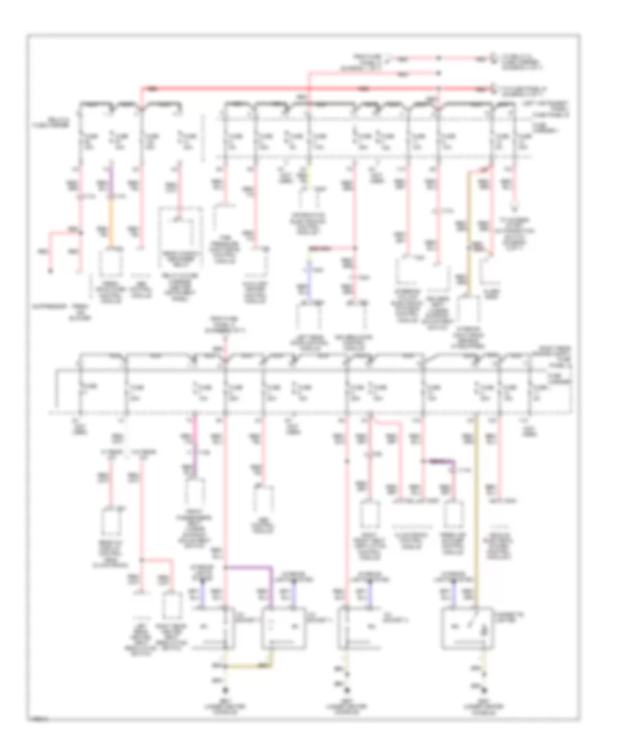
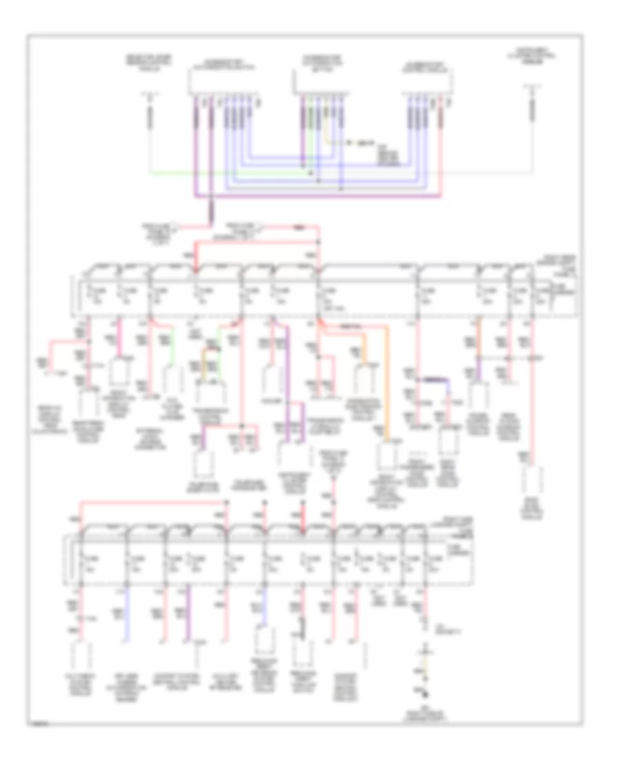
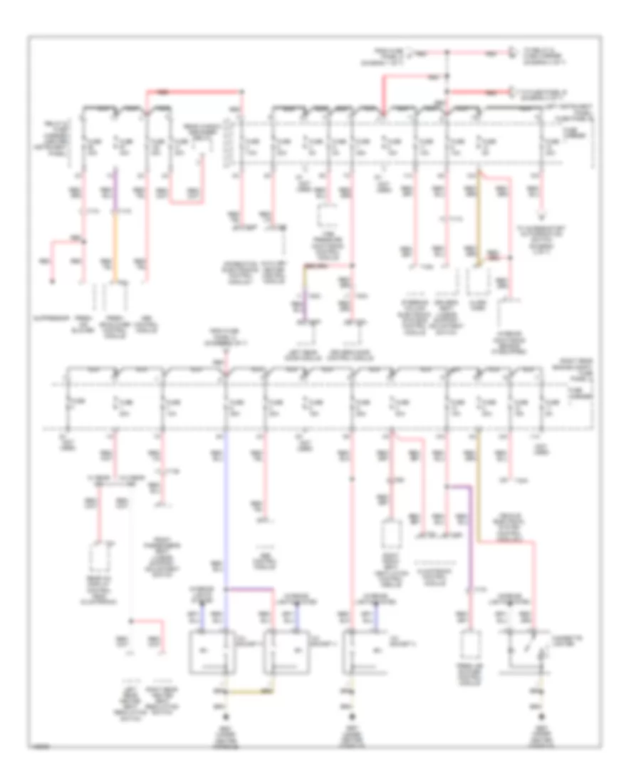
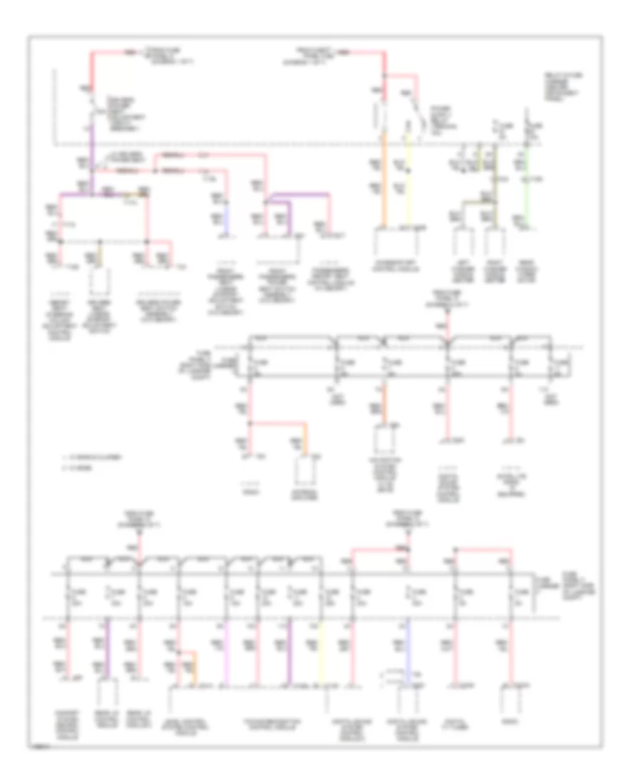
3.0L SC, Power Distribution Wiring Diagram (1 of 7) for Audi Q7 Prestige S 2013

List of elements for 3.0L SC, Power Distribution Wiring Diagram (1 of 7) for Audi Q7 Prestige S 2013:
- 11a
- 15)
- 16a
- 17a
- Access/start authorization control module
- Air bag control module
- Battery
- Battery interrupt igniter
- Battery jump start terminal
- Battery monitoring control module
- Coolant fan control (fc) control module
- Coolant fan control module 2
- Engine control module (ecm)
- Fuel pump (fp) control module
- Fuse 150a
- Fuse 30a
- Fuse 40a
- Fuse 50a
- Fuse 5a
- Fuse 60a
- Fuse panel d (below driver's seat)
- Generator & voltage regulator
- Ignition coil 1 w/ power output stage
- Ignition coil 2 w/ power output stage
- Ignition coil 3 w/ power output stage
- Ignition coil 4 w/ power output stage
- Ignition coil 5 w/ power output stage
- Ignition coil 6 w/ power output stage
- Inal
- Level control system compressor relay
- Red
- Relay & fuse carrier
- Relay & fuse panel e-box (left side of plenum chamber)
- Secondary air injection (air) pump relay
- Starter
- Starter relay
- Starter relay 2
- T10d
- T17d
- T20e
- T2k
- T6k
- T94
- To fuse panel b (diagram 2 of 7)
- To fuse panel b (diagram 5 of 7)
- To fuse panel c (diagram 2 of 7)
- To fuse panel c (diagram 3 of 7)
- To fuse panel c (diagram 6 of 7)
- To fuse panel f (diagram 5 of 7)
- To fuse panel f (diagram 6 of 7)
- To fuse panel f (diagram 7 of 7)
- To relay & fuse carrier (diagram 7 of 7)
- To relay & fuse panel e-box (diagram 4 of 7)
- To right instrument panel fuse carrier (diagram 3 of 7)
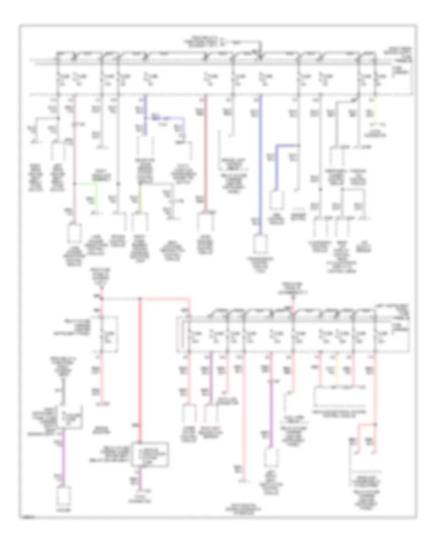
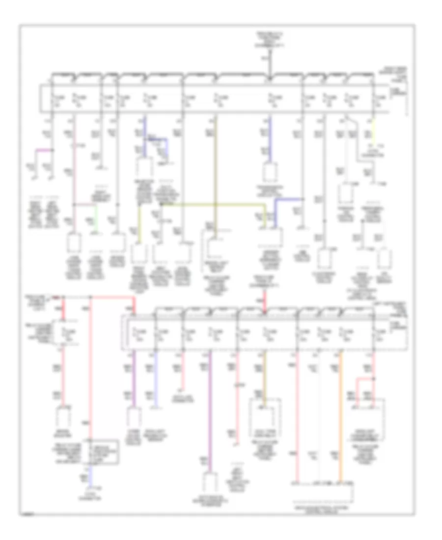
3.0L SC, Power Distribution Wiring Diagram (2 of 7) for Audi Q7 Prestige S 2013
List of elements for 3.0L SC, Power Distribution Wiring Diagram (2 of 7) for Audi Q7 Prestige S 2013:
- (left instrument panel) fuse panel b
- (not used)
- (right rear engine compt) fuse panel c
- 10a
- 11a
- 12a
- 12v socket 2
- 12v socket 3
- 12v socket 4
- Abs control module
- Alarm horn
- Auxiliary heater control module
- Cigarette lighter
- Climatronic control module
- Driver's door control module
- Driver's seat lumbar support adjustment switch
- Fresh air blower
- Fresh air blower control module
- From fuse panel d (diagram 1 of 7)
- Front passenger's seat lumbar support adjustment switch
- Fuse
- Fuse 10a
- Fuse 15a
- Fuse 20a
- Fuse 25a
- Fuse 30a
- Fuse 35a
- Fuse 40a
- Fuse 5a
- Fuse 7.5a
- Fuse carrier
- Fuse carrier 1
- G687 (under center console)
- Information electronics control module 1
- Interior lights system
- Interior monitoring sensor (if equipped)
- Left rear door control module
- Left rear heated seat regulating switch
- Nca
- Rear a/c display control head (climatronic)
- Rear window defogger relay
- Red
- Relay & fuse carrier
- Relay & fuse carrier (center instrument panel)
- Right front seat ventilation control module
- Right rear heated seat regulating switch
- Steering column electronic systems control module
- Suppressor
- T16a
- T16d
- T17a
- T17b
- T17h
- T17k
- T20a
- T20c
- T20l
- T20n
- T2b
- T3c
- T3h
- T40a
- T6ai
- T6g
- T8af
- Tire pressure monitoring control module
- To access/ start authorization switch (diagram 6 of 7)
- To fuse panel b (diagram 3 of 7)
- To relay & fuse carrier (diagram 3 of 7)
- Vehicle electrical system control module 2
- W/ rear a/c
- W/o rear a/c
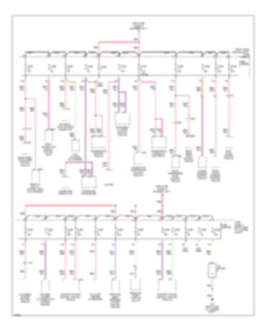
3.0L SC, Power Distribution Wiring Diagram (3 of 7) for Audi Q7 Prestige S 2013
List of elements for 3.0L SC, Power Distribution Wiring Diagram (3 of 7) for Audi Q7 Prestige S 2013:
- (left instrument panel) fuse panel b
- (right rear engine compt) fuse panel c
- 10a
- 11a
- 12 pin connector
- 12a
- 18 pin connector
- Abs control module
- Air bag control module
- Air quality sensor
- Asr/esp button
- Brake booster
- Brake light disable relay
- Climatronic control module
- Cooler
- Cooler fuse 5a
- Data bus on board diagnostic interface
- Data link connector
- Dual horn relay
- From fuse panel b (diagram 2 of 7)
- From relay & fuse panel e-box (diagram 1 of 7)
- Front pass- enger's air bag disabled indicator lamp
- Fuse 10a
- Fuse 15a
- Fuse 25a
- Fuse 30a
- Fuse 5a
- Fuse carrier
- Headlamp washer relay (if equipped)
- Lane change assistance control module
- Lane change assistance control module 2
- Left front seat ventilation control module
- Left rear heated seat regul- ating switch
- Level control system control module
- Multi- function transmission range (tr) switch
- Nca
- Parking aid control module
- Peripheral camera control module
- Rain/light recognition sensor
- Rear a/c display control head (w/ climatronic display & control head)
- Red
- Relay & fuse carrier (center instrument panel)
- Relay & fuse carrier under driver seat (below driver seat)
- Right headlamp assembly
- Right instrument panel fuse carrier (right rear engine compt)
- Right rear heated seat regul- ating switch
- Seat occupied recognition control module
- Selector lever sensor system control module
- T10a
- T12b
- T12z
- T14d
- T14h
- T16b
- T16d
- T16h
- T17b
- T18
- T18e
- T4y
- T6f
- T81a
- Transmission control module (tcm)
- Vehicle electrical system control module
- Vehicle positioning system fuse 5a
- Wiper motor control module
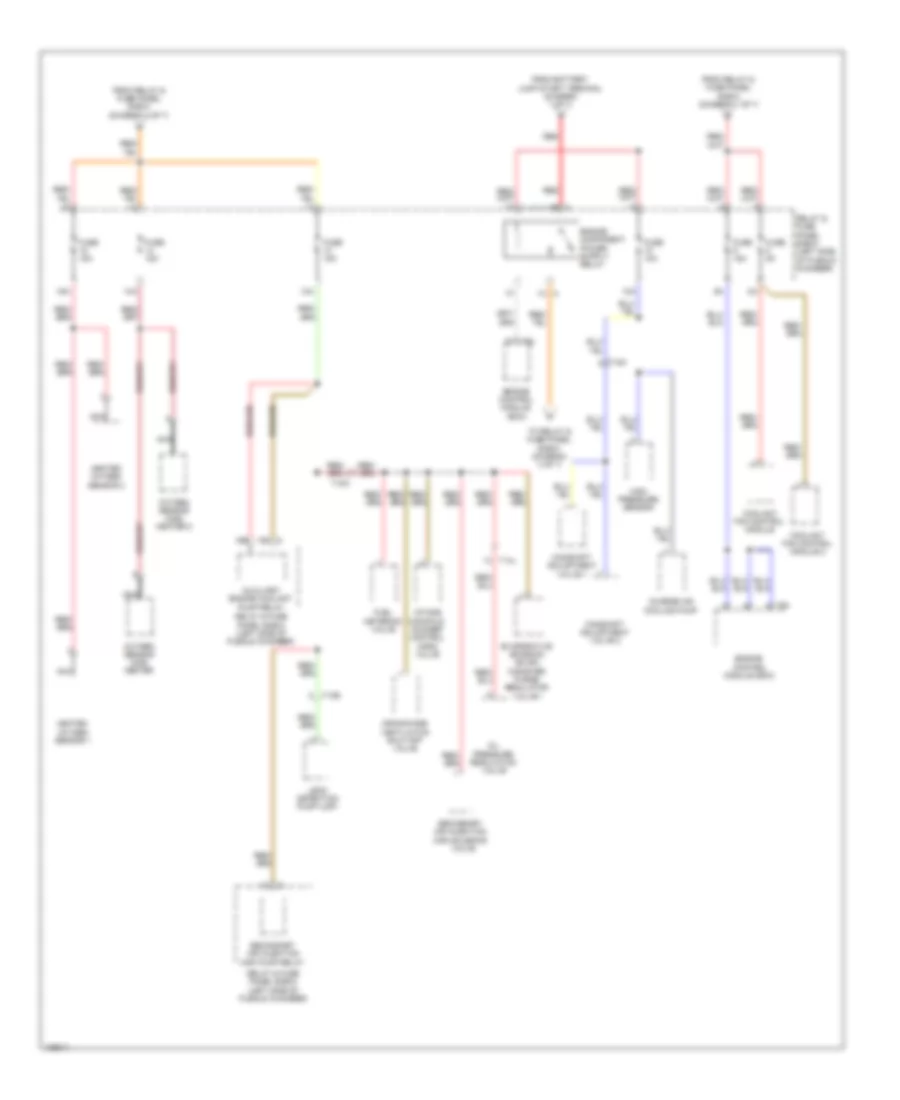
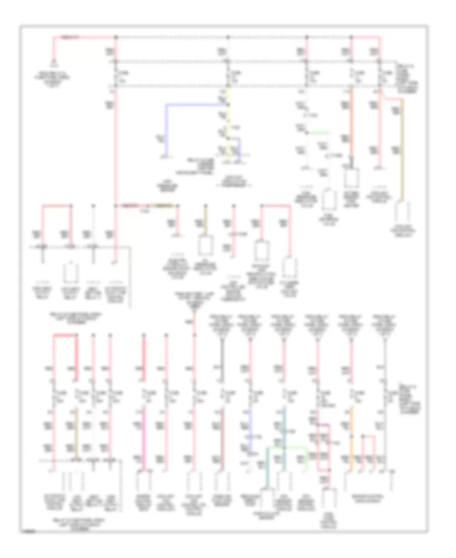
3.0L SC, Power Distribution Wiring Diagram (4 of 7) for Audi Q7 Prestige S 2013
List of elements for 3.0L SC, Power Distribution Wiring Diagram (4 of 7) for Audi Q7 Prestige S 2013:
- 10a
- 13a
- 14a
- 15a
- 19c c
- 19e
- 1b a
- 1h a
- Auxiliary engine coolant pump relay
- Camshaft adjustment valve 1
- Camshaft adjustment valve 2
- Charge air cooling pump
- Coolant fan control module
- Coolant fan control module 2
- Crankcase ventilation shut-off valve
- Engine control module (ecm)
- Evaporative emission (evap) canister purge regulator valve 1
- From battery jump start terminal (diagram 1 of 7)
- From relay & fuse panel e-box (diagram 1 of 7)
- From relay & fuse panel e-box (diagram 4 of 7)
- Fuel metering valve
- Fuse 10a
- Fuse 15a
- Fuse 5a
- Heated oxygen sensor 1
- Heated oxygen sensor 2
- High pressure sensor
- Intake manifold runner control (imrc) valve
- Leak detection pump (ldp)
- Nca
- Oil pressure regulation valve
- Oxygen sensor (o2s) heater
- Oxygen sensor (o2s) heater 2
- Red
- Relay & fuse panel e-box (left side of plenum chamber)
- Secondary air injection (air) pump relay
- Secondary air injection (air) solenoid
- T10e
- T10m
- T14l
- T94
- To relay & fuse panel e-box (diagram 4 of 7)
- Valve
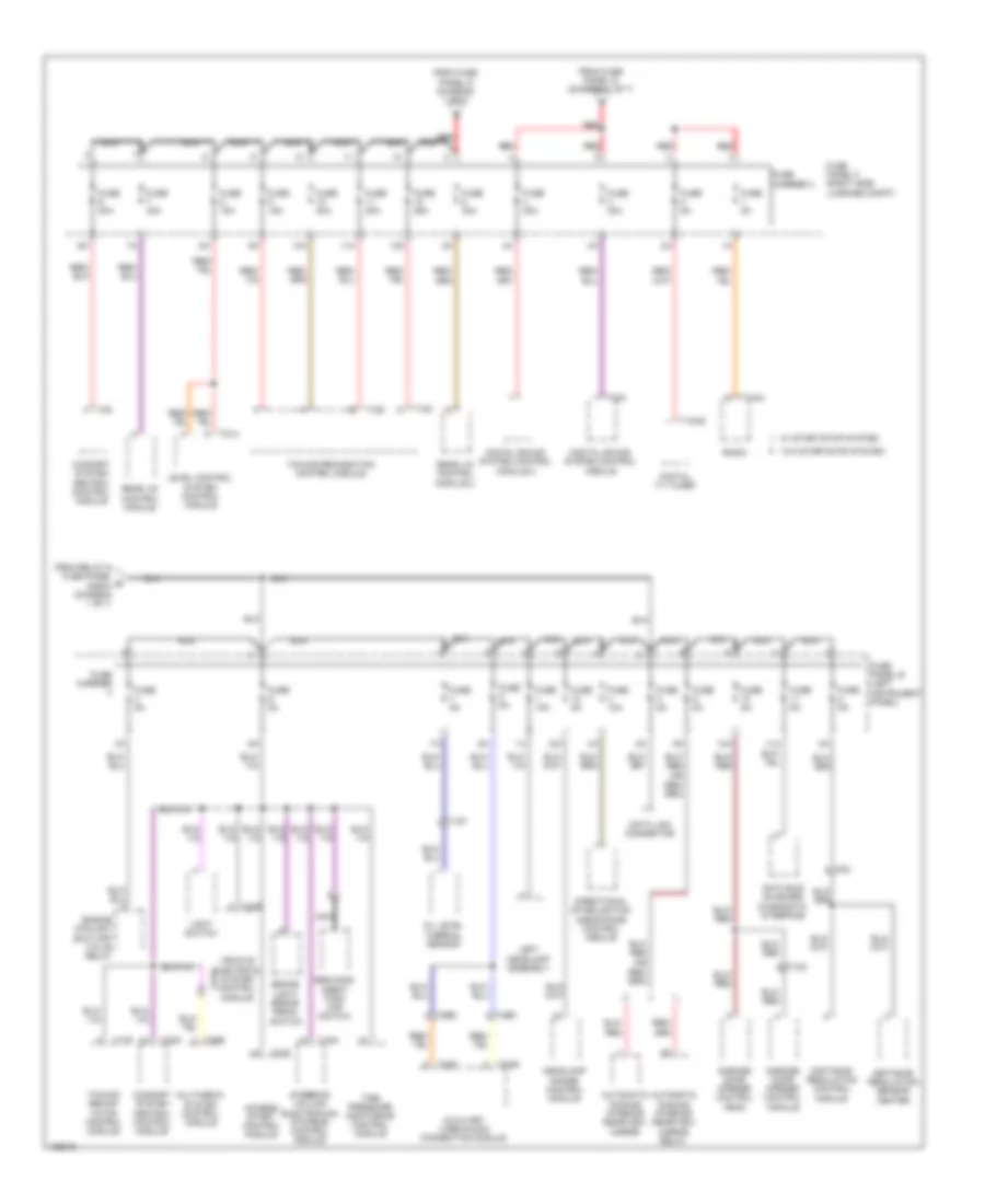
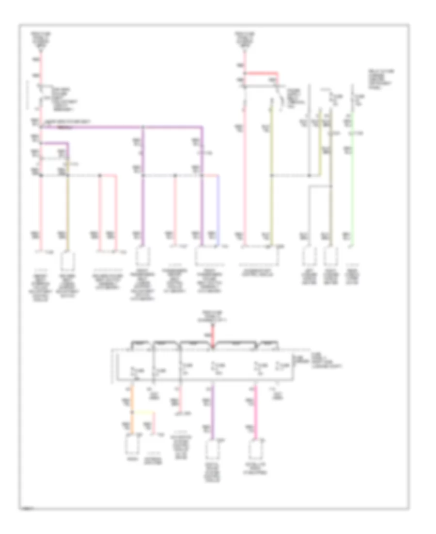
3.0L SC, Power Distribution Wiring Diagram (5 of 7) for Audi Q7 Prestige S 2013
List of elements for 3.0L SC, Power Distribution Wiring Diagram (5 of 7) for Audi Q7 Prestige S 2013:
- 10a
- 10g
- 11a
- 12a
- Access/ start control module
- Automatic dimming interior rearview mirror
- Automatic dimming interior rearview mirror relay
- Auxiliary video/audio connection module
- Brake light/ brake pedal switch
- Comfort system central control module
- Data bus on board diagnostic interface
- Data link connector
- Digital sound system control module
- Digital sound system control module 2
- Digital tv tuner
- Directional stabilization assistance control module
- Distance regulation control module
- Distance regulation sensor heater
- Engine coolant shut-off valve relay
- From fuse panel d (diagram 1 of 7)
- From relay & fuse panel g e-box (diagram 1 of 7)
- Fuse 10a
- Fuse 15a
- Fuse 20a
- Fuse 25a
- Fuse 30a
- Fuse 5a
- Fuse carrier
- Fuse carrier 3
- Fuse panel b (left instrument panel)
- Fuse panel f (right side luggage compt)
- Garage door opener control head
- Garage door opener control module
- Headlamp range control module
- Left headlamp assembly
- Level control system control module
- Light switch
- Multimedia system control module
- Nca
- Oil level thermal sensor
- Radio
- Rear lid control module
- Rear lid control module 2
- Red
- Reducing agent tank cap switch
- Steering column electronics systems control module
- T10aa
- T10f
- T10o
- T12ag
- T12c
- T12d
- T16a
- T20e
- T26e
- T2bc
- T2bd
- T32b
- T32c
- T32d
- T3ae
- T3af
- T4ai
- T81a
- T8c
- Tire pressure monitoring control module
- Towing recog- nition control module
- Towing recognition control module
- Vehicle electrical system control module
- W/ start/stop system
- W/o start/stop system
3.0L SC, Power Distribution Wiring Diagram (6 of 7) for Audi Q7 Prestige S 2013
List of elements for 3.0L SC, Power Distribution Wiring Diagram (6 of 7) for Audi Q7 Prestige S 2013:
- (not used)
- (or 7.5a)
- (right rear engine compt) fuse panel c
- (right side luggage compt) fuse panel f
- 10a
- 11a
- 12a
- 12v socket 5
- 4a (not used)
- Access/start authorization
- Access/start authorization switch
- Access/start control module
- Auxiliary heater rf recever
- Button
- Comfort system central control module
- Comfort system central control module 2
- Cooler
- Dvd player & cd changer
- External audio source connector
- From fuse k panel d (diagram 1 of 7)
- From fuse o panel b (diagram 2 of 7)
- From fuse panel d (diagram 1 of 7)
- Front information display control head
- Front information display control head control module
- Front passenger's door control module
- Fuse 10a
- Fuse 15a
- Fuse 20a
- Fuse 30a
- Fuse 35a
- Fuse 5a
- Fuse carrier
- G45 (behind center of dash)
- G51 (right side of luggage compt)
- Information electronics control module 1
- Instrument cluster control
- Instrument cluster control module
- Keyless access authorization antenna reader
- Module
- Multimedia system control module
- Nca
- Power sunroof control module
- Rear a/c display control head (climatronic)
- Rear fresh air blower control module
- Rear sliding sunroof control module
- Red
- Reducing agent metering system control module
- Reducing agent tank cap switch
- Right rear door control module
- Roof blind control module
- Selector lever sensor control module
- T10g
- T16h
- T17h
- T20b
- T20d
- T20e
- T20k
- T20m
- T20o
- T2a
- T3a
- T4ai
- T4u
- T6a
- T6y
- T8a
- T8ad
- T8af
- T8i
- Telephone base plate
- Telephone transceiver
- Transmission control module
- Transmission hydraulic pump relay
3.0L SC, Power Distribution Wiring Diagram (7 of 7) for Audi Q7 Prestige S 2013
List of elements for 3.0L SC, Power Distribution Wiring Diagram (7 of 7) for Audi Q7 Prestige S 2013:
- (not used)
- 11a
- 30a
- Access/start control module
- Antenna amplifier
- Digital sound system control module
- Driver's power seat adjustment circuit breaker 1
- Driver's power seat switch assembly (w/o memory)
- Driver's seat lumbar support adjustment switch
- From fuse panel d (diagram 1 of 7)
- Front passenger's power seat switch assembly (w/o memory)
- Front passenger's seat lumbar support adjustment switch (w/o memory)
- Fuse
- Fuse 15a
- Fuse 30a
- Fuse 5a
- Fuse carrier
- Fuse panel f (right side luggage compt)
- Left washer nozzle heater
- Memory seat/ steering column adjustment control module
- Navigation system control module (w/ cd drive)
- Nca
- Passenger's memory seat control module (w/ memory)
- Radio
- Rear window wiper motor
- Red
- Relay & fuse carrier (center instrument panel)
- Right washer nozzle heater
- Satellite radio (if equipped)
- T10r
- T12s
- T12t
- T17a
- T17b
- T20e
- T2w
- T32c
- T3q
- T4x
- T8k
- T8l
- T8n
- W/ driver's power seat
3.0L TURBO DIESEL
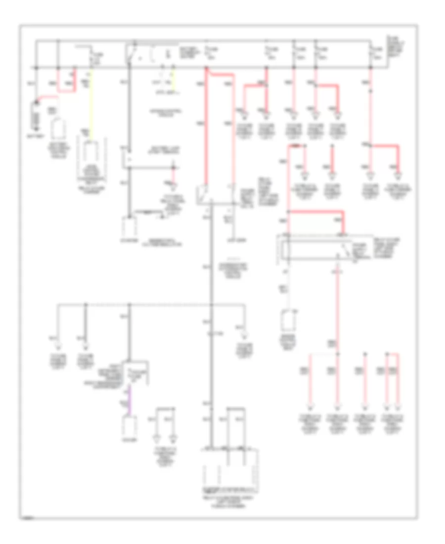
3.0L Turbo Diesel, Power Distribution Wiring Diagram (1 of 7) for Audi Q7 Prestige S 2013
List of elements for 3.0L Turbo Diesel, Power Distribution Wiring Diagram (1 of 7) for Audi Q7 Prestige S 2013:
- 2b a
- Access/start authorization control module
- Air bag control module
- Battery
- Battery interrupt igniter
- Battery jump start terminal
- Battery monitoring control module
- Cooler
- Cooler fuse 5a
- Engine control module (ecm)
- Fuse 150a
- Fuse 40a
- Fuse 50a
- Fuse 60a
- Fuse panel d (below driver seat)
- Generator & voltage regulator
- Level control system compressor relay
- Red
- Relay & fuse carrier
- Relay & fuse panel e-box (left side of plenum chamber)
- Right instrument panel fuse carrier (right rear engine compartment)
- Starter
- Starter relay
- Starter relay 2
- T10d
- T20e
- T91
- To fuse & relay panel e-box (diagram 6 of 7)
- To fuse panel b (diagram 2 of 7)
- To fuse panel b (diagram 3 of 7)
- To fuse panel c (diagram 3 of 7)
- To fuse panel c (diagram 4 of 7)
- To fuse panel c (diagram 5 of 7)
- To fuse panel f (diagram 5 of 7)
- To fuse panel f (diagram 7 of 7)
- To relay & fuse carrier (diagram 7 of 7)
- To relay & fuse panel e-box (diagram 6 of 7)
3.0L Turbo Diesel, Power Distribution Wiring Diagram (2 of 7) for Audi Q7 Prestige S 2013
List of elements for 3.0L Turbo Diesel, Power Distribution Wiring Diagram (2 of 7) for Audi Q7 Prestige S 2013:
- (left instrument panel) fuse panel b
- 10a
- 11a
- 12a
- Access/ start control module
- Access/start authorization button
- Access/start authorization switch
- Access/start control module
- Automatic dimming interior rearview mirror
- Automatic dimming interior rearview mirror relay
- Auxiliary video/ audio connection module
- Brake light/ brake pedal switch
- Comfort system central control module
- Data bus on board diagnostic interface
- Data link connector
- Directional stabilization assistance control module
- Distance regulation control module
- Distance regulation sensor heater
- Engine coolant shut-off valve relay
- From fuse panel b (diagram 3 of 7)
- From relay t & fuse panel e-box (diagram 1 of 7)
- From relay x & fuse panel e-box (diagram 1 of 7)
- Fuse 10a
- Fuse 5a
- Fuse carrier
- G45 (behind center of dash)
- Garage door opener control head
- Garage door opener control module
- Headlamp range control module
- Instrument cluster control
- Left headlamp assembly
- Light switch
- Module
- Multimedia system control module
- Nca
- Oil level thermal sensor
- Reducing agent tank cap switch
- Selector lever sensor control module
- Steering column electronic systems control module
- T10f
- T10o
- T12d
- T16a
- T20e
- T26e
- T2a
- T2bc
- T2bd
- T32b
- T32d
- T3a
- T3ae
- T3af
- T4ai
- T6a
- T8a
- T8c
- Tire pressure monitoring control module
- Towing recog- nition control module
- Vehicle electrical system control module
- W/ start/stop system w/ start/stop system
- W/o start/stop system
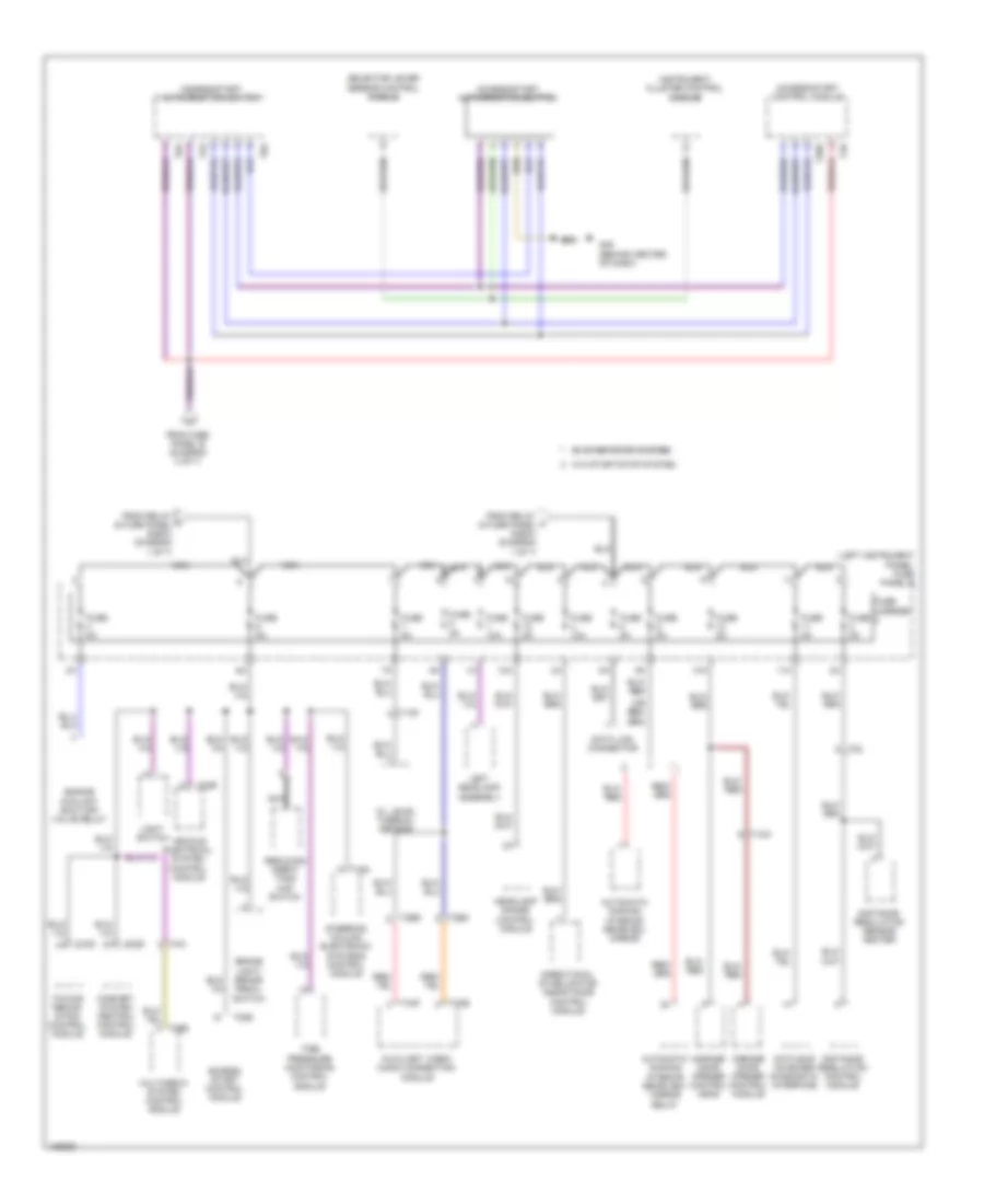
3.0L Turbo Diesel, Power Distribution Wiring Diagram (3 of 7) for Audi Q7 Prestige S 2013
List of elements for 3.0L Turbo Diesel, Power Distribution Wiring Diagram (3 of 7) for Audi Q7 Prestige S 2013:
- (left instrument panel) fuse panel b
- (not used)
- (right rear engine compt) fuse panel c
- 10a
- 11a
- 12a
- 12v socket 2
- 12v socket 3
- 12v socket 4
- 2a (not used)
- Abs control module
- Alarm horn
- Auxiliary heater control module
- Cigarette lighter
- Climatronic control module
- Driver's door control module
- Driver's seat lumbar support adjustment switch
- Fresh air blower
- Fresh air blower control module
- From fuse panel d (diagram 1 of 7)
- Front passenger's seat lumbar support adjustment switch
- Fuse
- Fuse 10a
- Fuse 15a
- Fuse 20a
- Fuse 25a
- Fuse 30a
- Fuse 35a
- Fuse 40a
- Fuse 5a
- Fuse 7.5a
- Fuse carrier
- G687 (under center console)
- Information electronics control module 1
- Interior lights system
- Interior monitoring sensor (if equipped)
- Left rear door module
- Left rear heated seat regulating switch
- Nca
- Rear a/c display control head (climatronic)
- Rear window defogger relay
- Red
- Relay & fuse carrier (center instrument panel)
- Right front seat ventilation control module
- Right rear heated seat regulating switch
- Steering column electronic systems control module
- Suppressor
- T16a
- T16d
- T17a
- T17b
- T17h
- T17k
- T20a
- T20c
- T20l
- T20n
- T2b
- T3c
- T3h
- T40a
- T6ai
- T6g
- T8af
- Tire pressure monitoring control module
- To access/start authorization switch (diagram 2 of 7)
- To fuse panel b (diagram 4 of 7)
- To relay & fuse carrier (diagram 4 of 7)
- Vehicle electrical system control module 2
- W/ rear a/c
- W/o rear a/c
3.0L Turbo Diesel, Power Distribution Wiring Diagram (4 of 7) for Audi Q7 Prestige S 2013
List of elements for 3.0L Turbo Diesel, Power Distribution Wiring Diagram (4 of 7) for Audi Q7 Prestige S 2013:
- (left instrument panel) fuse panel b
- (right rear engine compt) fuse panel c
- 10a
- 11a
- 12 pin connector
- 12a
- 18 pin connector
- Abs control module
- Air bag control module
- Air quality sensor
- Asr/esp button/ emergency flasher switch
- Brake booster
- Brake light disable relay
- Climatronic control module
- Data bus on board diagnostic interface
- Data link connector
- Dual tone horn relay
- From fuse panel b (diagram 3 of 7)
- From fuse r panel b (diagram 3 of 7)
- From relay & fuse panel e-box (diagram 1 of 7)
- Front pass- enger's air bag disabled indicator lamp
- Fuse 10a
- Fuse 15a
- Fuse 25a
- Fuse 30a
- Fuse 5a
- Fuse carrier
- Headlamp washer relay (if equipped)
- Lane change assis- tance control module
- Lane change assis- tance control module 2
- Left front seat ventilation control module
- Left rear heated seat regul- ating switch
- Level control system control module
- Multi- function transmission range (tr) switch
- Nca
- Parking aid control module
- Peripheral camera control module
- Rain/light recognition sensor
- Rear a/c display control head (w/ climatronic display & control head)
- Red
- Relay & fuse carrier (center instrument panel)
- Relay & fuse carrier under driver seat (below driver seat)
- Right headlamp assembly
- Right rear heated seat regul- ating switch
- Seat occupied recognition control module
- Selector lever sensor system control module
- T10a
- T12b
- T12z
- T14d
- T14h
- T16b
- T16d
- T16h
- T17b
- T18
- T18e
- T4y
- T6f
- T81a
- Transmission control module (tcm)
- Vehicle electrical system control module
- Vehicle positioning system fuse 5a
- Wiper motor control module
3.0L Turbo Diesel, Power Distribution Wiring Diagram (5 of 7) for Audi Q7 Prestige S 2013
List of elements for 3.0L Turbo Diesel, Power Distribution Wiring Diagram (5 of 7) for Audi Q7 Prestige S 2013:
- (not used)
- (or 5a)
- (right rear engine compt) fuse panel c
- 10a
- 11a
- 12a
- 12v socket
- Auxiliary heater rf recever
- Comfort system central control module
- Comfort system central control module 2
- Cooler
- Dvd player & cd changer
- External audio source connector
- From fuse panel d (diagram 1 of 7)
- Front information display control head
- Front passenger's door control module
- Fuse
- Fuse 10a
- Fuse 15a
- Fuse 20a
- Fuse 30a
- Fuse 35a
- Fuse 5a
- Fuse 7.5a
- Fuse carrier
- Fuse panel f (right side of luggage compt)
- G51 (right side of luggage compt)
- Information electronics control module 1
- Instrument cluster control module
- Keyless access authorization antenna reader
- Multimedia system control module
- Nca
- Power sunroof control module
- Rear a/c display control head (climatronic)
- Rear fresh air blower control module
- Rear sliding sunroof control module
- Red
- Reducing agent metering system control module
- Reducing agent tank cap switch
- Right rear door control module
- Roof blind control module
- T10g
- T16h
- T17h
- T20b
- T20d
- T20m
- T2o0
- T4ai
- T4u
- T6y
- T8ad
- T8af
- T8i
- Telephone base plate
- Telephone transceiver
- Transmission control module
- Transmission hydraulic pump relay
3.0L Turbo Diesel, Power Distribution Wiring Diagram (6 of 7) for Audi Q7 Prestige S 2013
List of elements for 3.0L Turbo Diesel, Power Distribution Wiring Diagram (6 of 7) for Audi Q7 Prestige S 2013:
- 10a
- 11a
- 12a
- 13a
- 14a
- 15a
- 16a
- 17a
- 18a
- 1d b
- 4c b
- 8al
- Automatic glow time control module
- B 1b
- B 3a
- B 3c
- B 4a
- Coolant circulation pump relay
- Coolant fan control (fc) control module
- Coolant fan control module
- Coolant fan control module 2
- Cylinder head coolant valve
- Electro hydraulic engine mount solenoid valve
- Engine control module (ecm)
- Exhaust gas recirculation (egr) cooler switch-over valve
- From battery jump start terminal (diagram 1 of 7)
- From relay & fuse panel e-box (diagram 1 of 7)
- Fuel metering valve
- Fuel pressure regulator valve
- Fuel pump control module
- Fuse 10a
- Fuse 15a
- Fuse 20a (or 25a)
- Fuse 40a
- Fuse 5a
- Fuse 60a
- Fuse 80a
- Heat setting relay 3
- High heat output relay
- High pressure sensor
- Low heat output relay
- Map controlled engine cooling thermostat
- Mass air flow (maf) sensor
- Nca
- Nox sensor control module
- Nox sensor control module 2
- Oil pressure regulation valve
- Oxygen sensor (o2s) heater
- Particulate sensor
- Red
- Reducing agent pump
- Relay & fuse carrier (center instrument panel)
- Relay & fuse panel e-box (left side of plenum chamber)
- T10ab
- T10d
- T10e
- T10m
- T17e
- T91
3.0L Turbo Diesel, Power Distribution Wiring Diagram (7 of 7) for Audi Q7 Prestige S 2013
List of elements for 3.0L Turbo Diesel, Power Distribution Wiring Diagram (7 of 7) for Audi Q7 Prestige S 2013:
- (diagram 1 of 7)
- (not used)
- 10a
- 10g
- 11a
- 12a
- 30a
- Access/start control module
- Antenna amplifier
- Comfort system central control module
- Digital sound system control module
- Digital sound system control module 2
- Digital tv tuner
- Driver's power seat adjustment circuit breaker 1
- Driver's power seat switch assembly (w/o memory)
- Driver's seat lumbar support adjustment switch
- From fuse panel d (diagram 1 of 7)
- From fuse panel d w
- Front passenger's power seat switch assembly (w/o memory)
- Front passenger's seat lumbar support adjustment switch (w/o memory)
- Fuse 15a
- Fuse 20a
- Fuse 25a
- Fuse 30a
- Fuse 5a
- Fuse carrier
- Fuse panel f (right side of luggage compt)
- Left washer nozzle heater
- Level control system control module
- Memory seat/ steering column adjustment control module
- Navigation system control module w/ cd drive
- Nca
- Passenger's memory seat control module (w/ memory)
- Radio
- Rear lid control module
- Rear lid control module 2
- Rear window wiper motor
- Red
- Relay & fuse carrier (center instrument panel)
- Right washer nozzle heater
- Satellite radio (if equipped)
- T10aa
- T10r
- T12ag
- T12c
- T12d
- T12s
- T12t
- T17a
- T17b
- T20e
- T2w
- T32c
- T38
- T3q
- T4x
- T81a
- T8k
- T8l
- T8n
- Towing recognition control module
- W/ bang & olufsen
- W/ bose
- W/ driver's power seat