INSTRUMENT CLUSTER
Instrument Cluster Wiring Diagram (1 of 2) for Audi A3 2009

List of elements for Instrument Cluster Wiring Diagram (1 of 2) for Audi A3 2009:
- Abs warning lamp
- Air bag malfunction ind lamp
- Anti-theft immobilizer reading coil
- Asr/esp control lamp
- Brake fluid level warning switch (in brake fluid reservoir cap)
- Brake pad wear ind lamp
- Computer data lines system
- Cruise control ind lamp
- Door ajar indicator lamp
- Early production
- Engine coolant level (ecl) warning switch (on coolant reservoir)
- Engine coolant level/ temperature (ecl/ect) warning lamp
- Engine coolant temperature gauge
- Engine electronic ind lamp
- Fuel filler lid lock warning lamp
- Fuel gauge
- Fuel level sensor 2 (awd)
- Fuel reserve warning lamp
- Fuse 17 fuse 6 5a
- Fuse 5a
- Fuse panel b (integrated in engine compartment e-box)
- Fuse panel c
- G42
- Generator warning lamp ind
- High beam ind lamp
- Hot at all times
- Instrument cluster control module (behind instrument cluster)
- Late production
- Left front brake pad wear sensor
- Left turn signal ind lamp
- Malfunction ind lamp (mil)
- Oil pressure warning lamp
- Outside air temperature display
- Outside air temperature sensor (behind left side of front bumper)
- Parking brake ind lamp & brake system warning lamp
- Parking light ind lamp
- Radio frequency controlled clock
- Rear hatch/ trunk lid ajar warning lamp
- Red
- Right turn signal ind lamp
- Steering column electronic systems control module (early production) (under steering column)
- T20b
- T40
- Tire pressure monitoring display ind lamp
- W/ high e-box
- W/ low e-box
- Warning buzzer & tone
- Windshield washer fluid level sensor
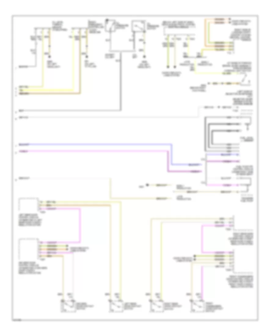
Instrument Cluster Wiring Diagram (2 of 2) for Audi A3 2009
List of elements for Instrument Cluster Wiring Diagram (2 of 2) for Audi A3 2009:
- (at base of parking brake lever assembly) parking brake warning light switch
- (below left side of dash) vehicle electrical system control module
- (left side of selector lever base) (a/t) selector lever sensor system control module
- (right side of luggage compt) comfort system central control module
- 2.0l
- 2.0l bpy
- 3.2l
- Computer data lines system
- Driver's door contact switch
- Driver's door control module (integrated in driver's door window regulator motor)
- Early production
- Except 2.0l bpy
- Front passenger's door contact switch
- Front passenger's door control module (integrated in right front door window regulator motor)
- Fuel level sensor
- Fuel pump (fp) control module (under right side of rear seat)
- G401
- G61 (on left "c" pillar)
- G638 (behind right kick panel)
- G655 (on left headlight)
- Late production
- Left rear door contact switch
- Left rear door control module (integrated in left rear door window regulator motor)
- Nca
- Oil level thermal sensor (if equipped)
- Oil pressure switch
- Radio frequency controlled clock receiver
- Right rear door contact switch
- Right rear door control module (integrated in right rear door window regulator motor)
- T10k
- T18
- T20f
- T20g
- T20n
- T20o
- T52a
- T52c
- Transfer fuel pump