POWER DISTRIBUTION
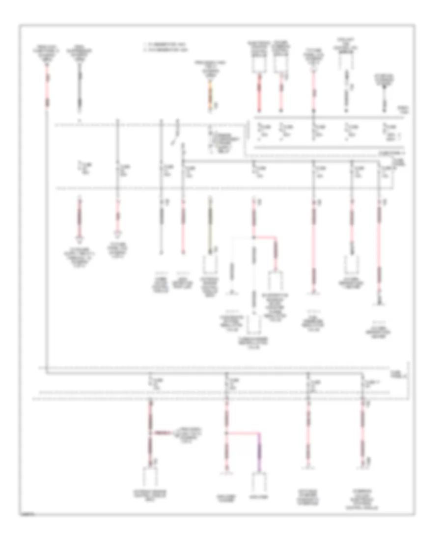
2.0L TURBO
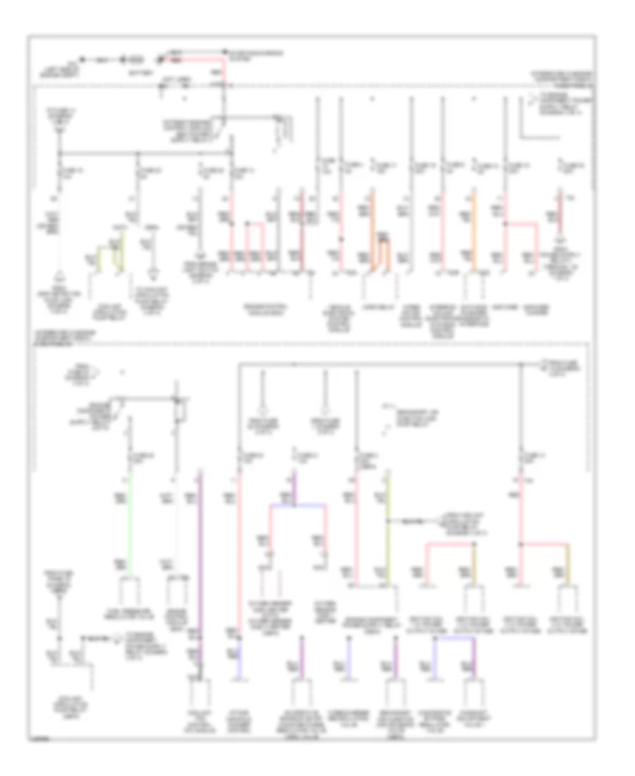
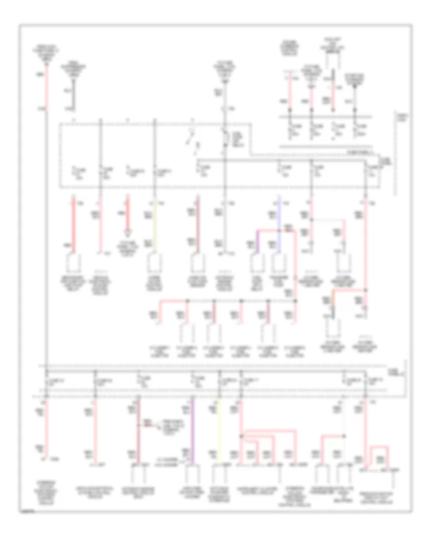
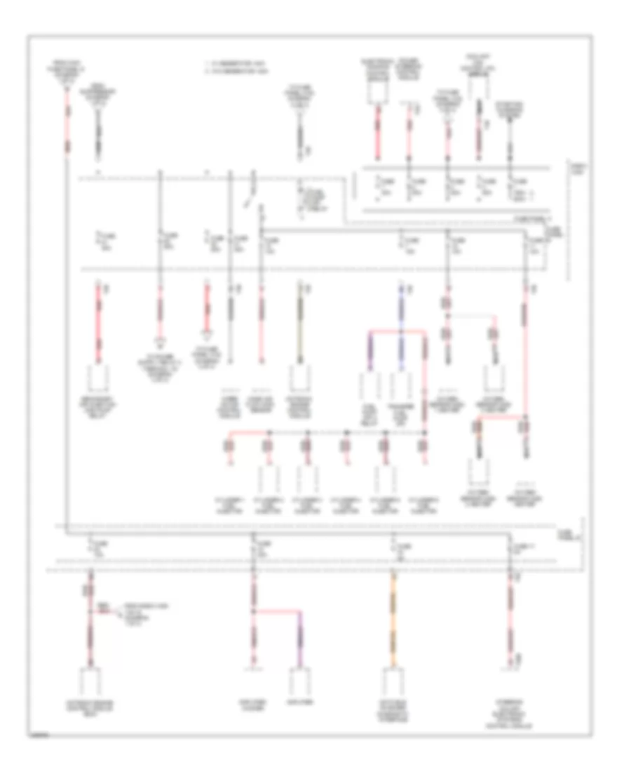
2.0L Turbo, Power Distribution Wiring Diagram, BPY Early Production (1 of 4) for Audi A3 2009

List of elements for 2.0L Turbo, Power Distribution Wiring Diagram, BPY Early Production (1 of 4) for Audi A3 2009:
- 20a
- 40a
- 41a
- 42a
- Air bag control module
- Air quality sensor
- Asr/esp button
- Automatic day/night interior mirror
- Backup light switch (m/t)
- Brake light switch
- Climatronic control module
- Data bus on board diagnostic interface
- Data link connector
- Direct shift gearbox (dsg) mechatronic
- Electronic damping control module
- Front passenger's air bag disabled indicator lamp
- Fuel pump control module
- Fuse 10a
- Fuse 15a
- Fuse 20 5a
- Fuse 40a
- Fuse 5a
- Fuse panel c
- G44 (behind left kick panel)
- Garage door opener control head
- Garage door opener control module
- Headlamp range control module
- High pressure sensor
- Left washer nozzle heater (if equipped)
- Light switch
- Load reduc- ction relay
- Mass air flow sensor
- Motronic engine control module (ecm)
- Oil level thermal sensor (if equipped)
- Parking aid control module
- Power steering control module
- Rear window wiper motor
- Red
- Right washer nozzle heater (if equipped)
- Seat occupied recognition control module
- Selector lever sensor system control module
- Solid state
- Starting/ charging system
- T100a
- T10b
- T10e
- T10k
- T11b
- T16d
- T16f
- T20d
- T20e
- T26b
- T2t
- T3w
- T47
- T6h
- T8h
- T94
- Vehicle electrical system control module
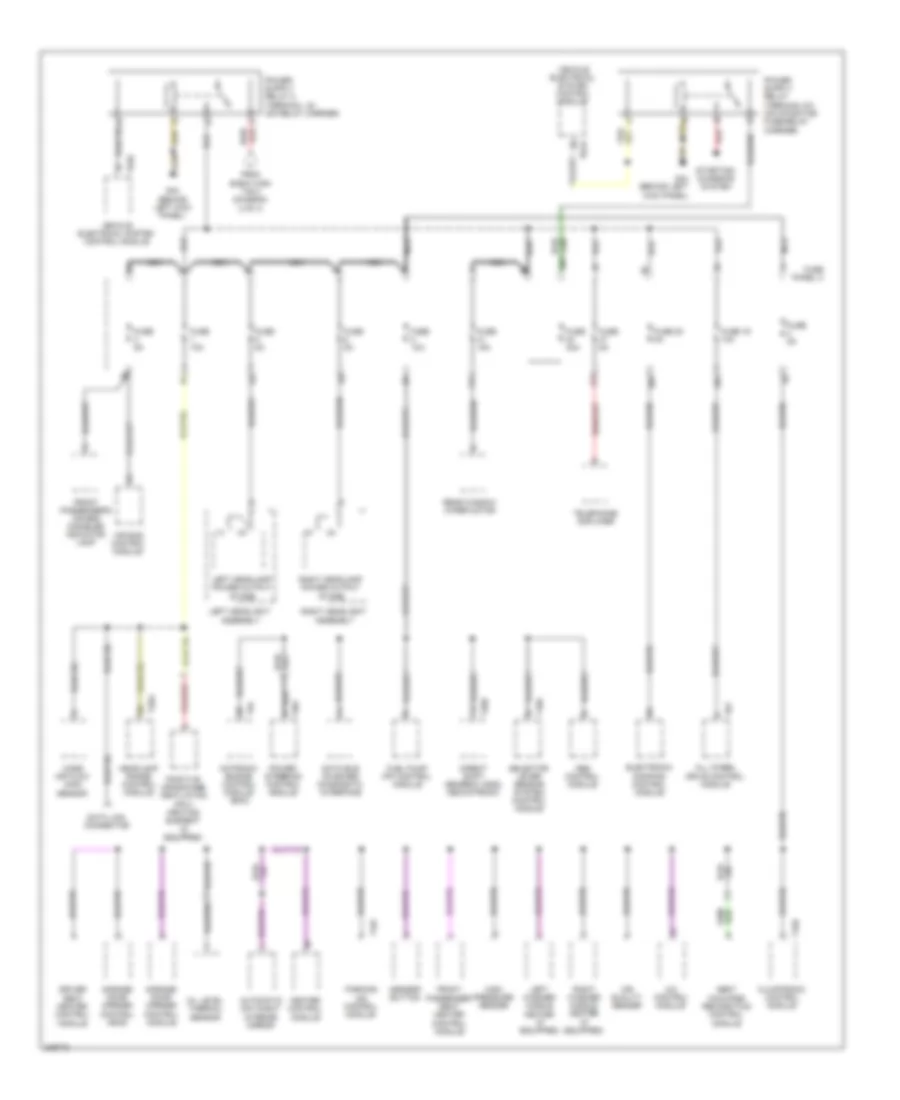
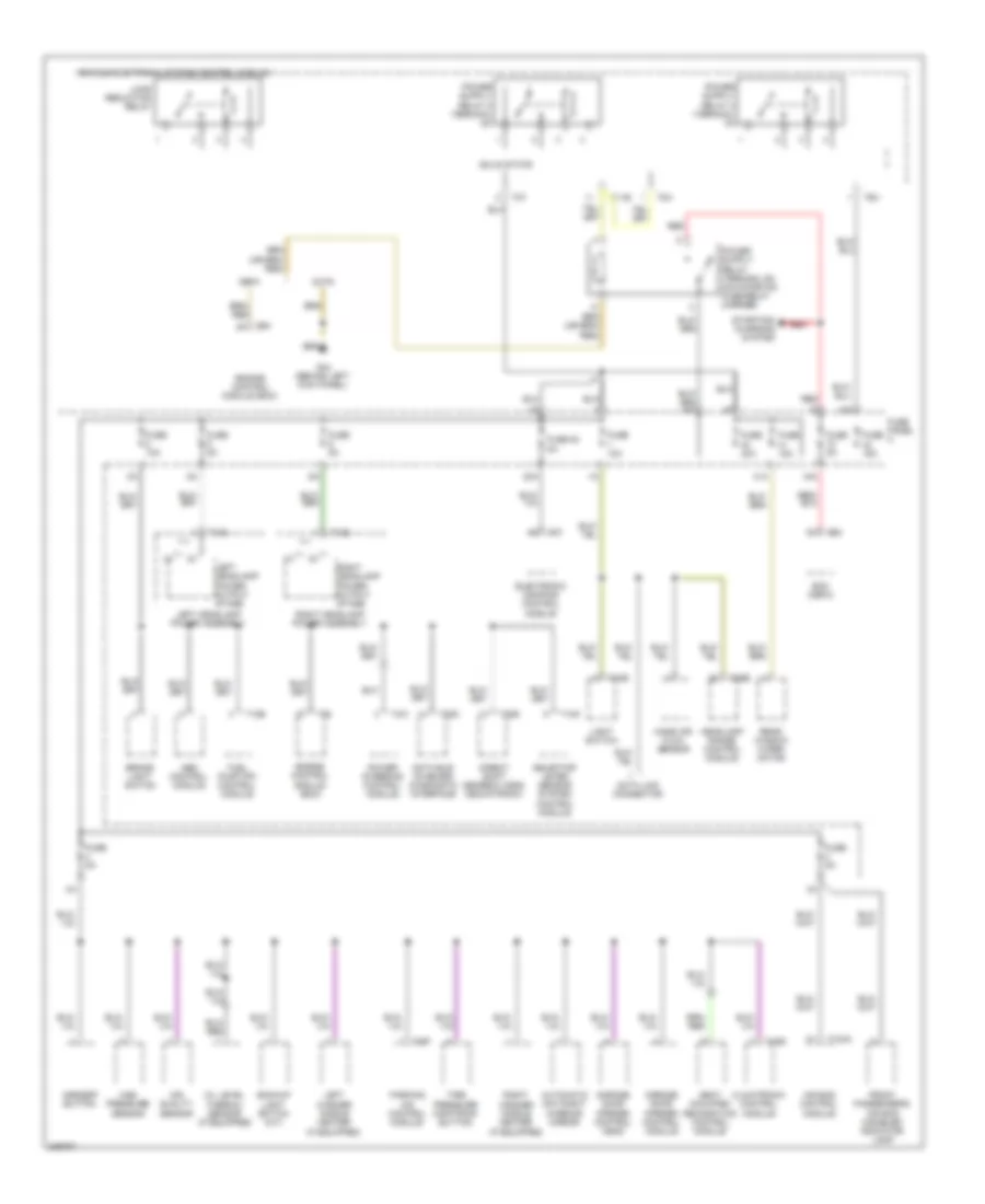
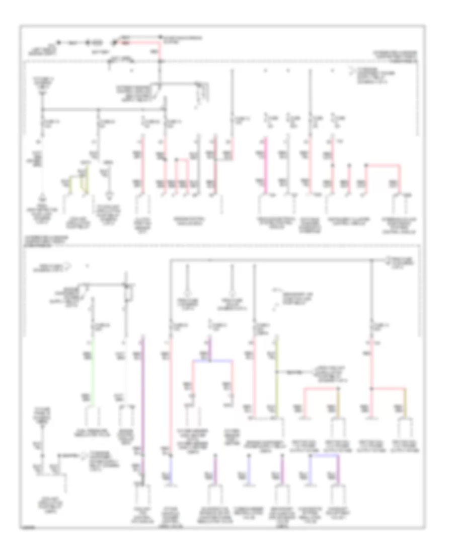
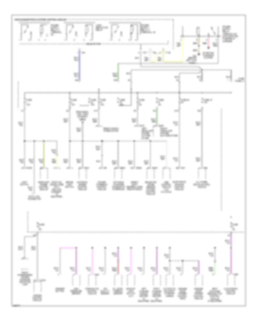
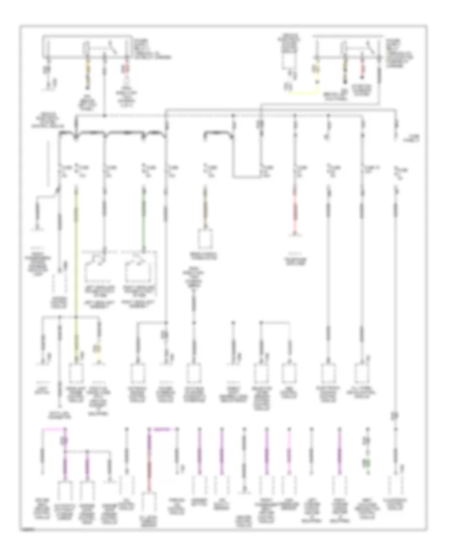
2.0L Turbo, Power Distribution Wiring Diagram, BPY Early Production (2 of 4) for Audi A3 2009
List of elements for 2.0L Turbo, Power Distribution Wiring Diagram, BPY Early Production (2 of 4) for Audi A3 2009:
- (integrated in engine compartment e-box) fuse panel b
- 30a
- Abs control module
- After- run coolant pump
- Coolant fan control (fc) module
- Direct shift gearbox (dsg) mechatronic
- Driver's seat adjustment switch
- Electronic damping control module
- Engine control module (ecm)
- Evaporative emission canister purge regulator valve
- Front passenger's seat adjustment switch
- Fuel pressure regulator valve
- Fuse 10a
- Fuse 150a (or 200a)
- Fuse 15a
- Fuse 2 fuse 4 20a
- Fuse 21 10a
- Fuse 28 15a
- Fuse 30a
- Fuse 40a
- Fuse 48 fuse 25 40a
- Fuse 50a
- Fuse 7 15a
- Fuse 80a
- Fuse panel a
- Generator
- Leak detection pump (ldp) (if equipped)
- Nca
- Oxygen sensor (o2s) heater 1
- Oxygen sensor (o2s) heater 3
- Oxygen sensor heater
- Power steering control module
- Preheating coolant high heat output relay
- Preheating coolant low heat output relay
- Red
- Safety fuse 1
- T20e
- T26
- T2a
- T40
- T47
- T4w
- T4x
- T94
- To coolant circulation pump relay (diagram 4 of 4)
- To fuse 23 (diagram 4 of 4)
- To fuse panel c (diagram 3 of 4)
- Turbocharger recirculating valve
- W/ high e-box
- W/ low e-box
- Wastegate bypass regulator valve
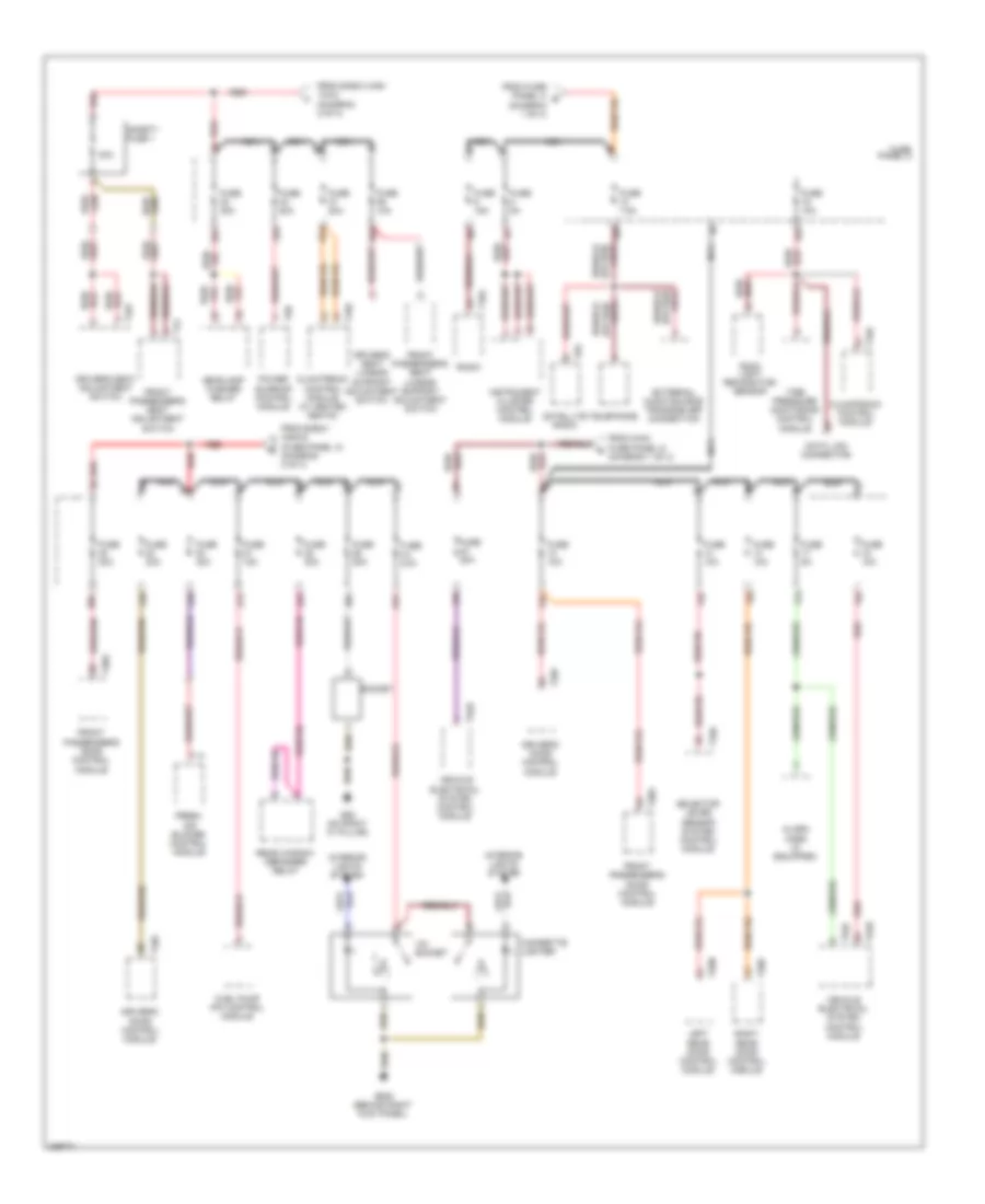
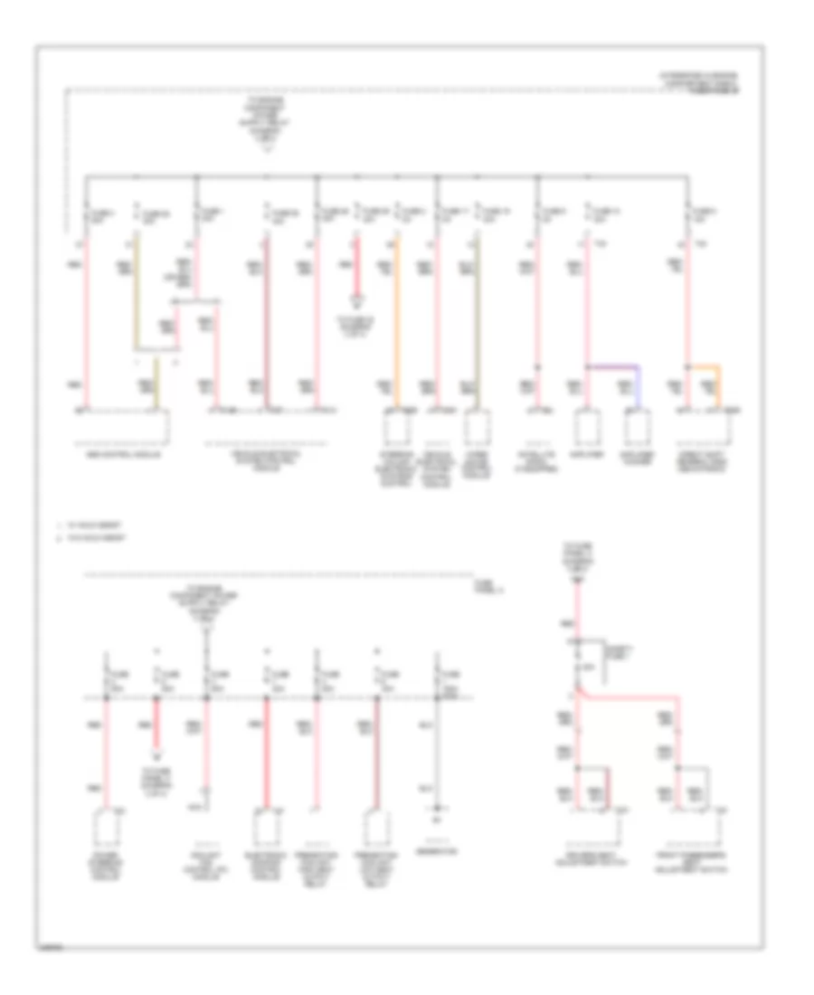
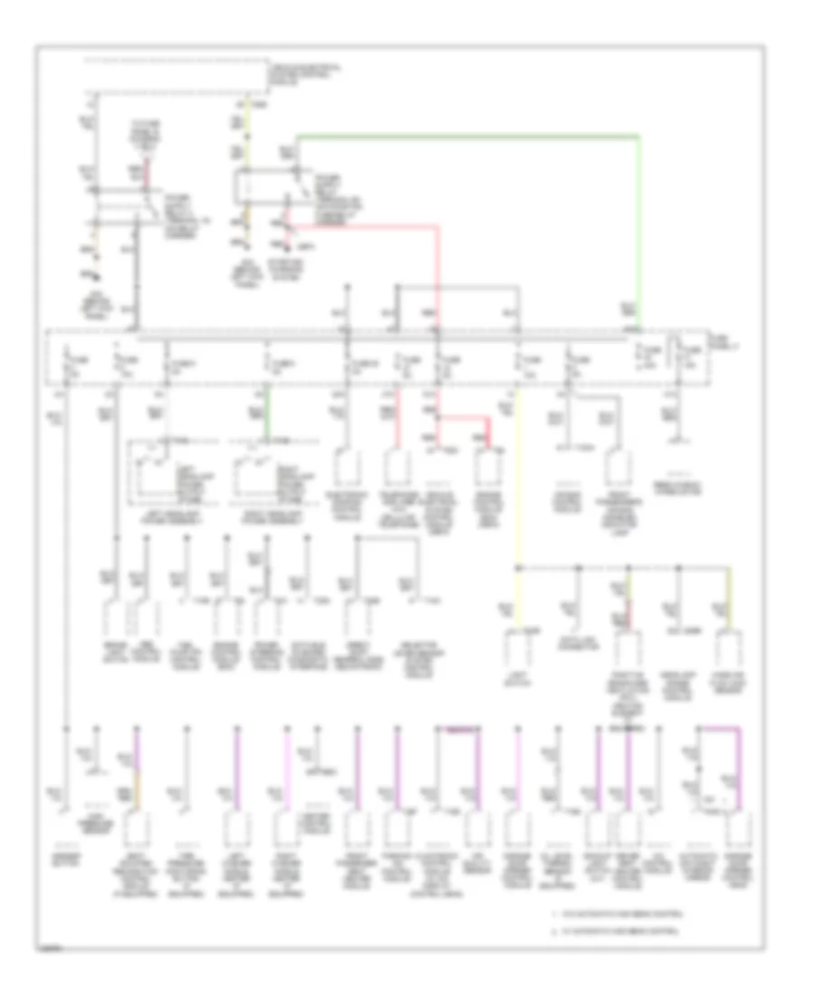
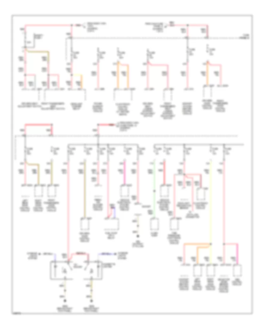
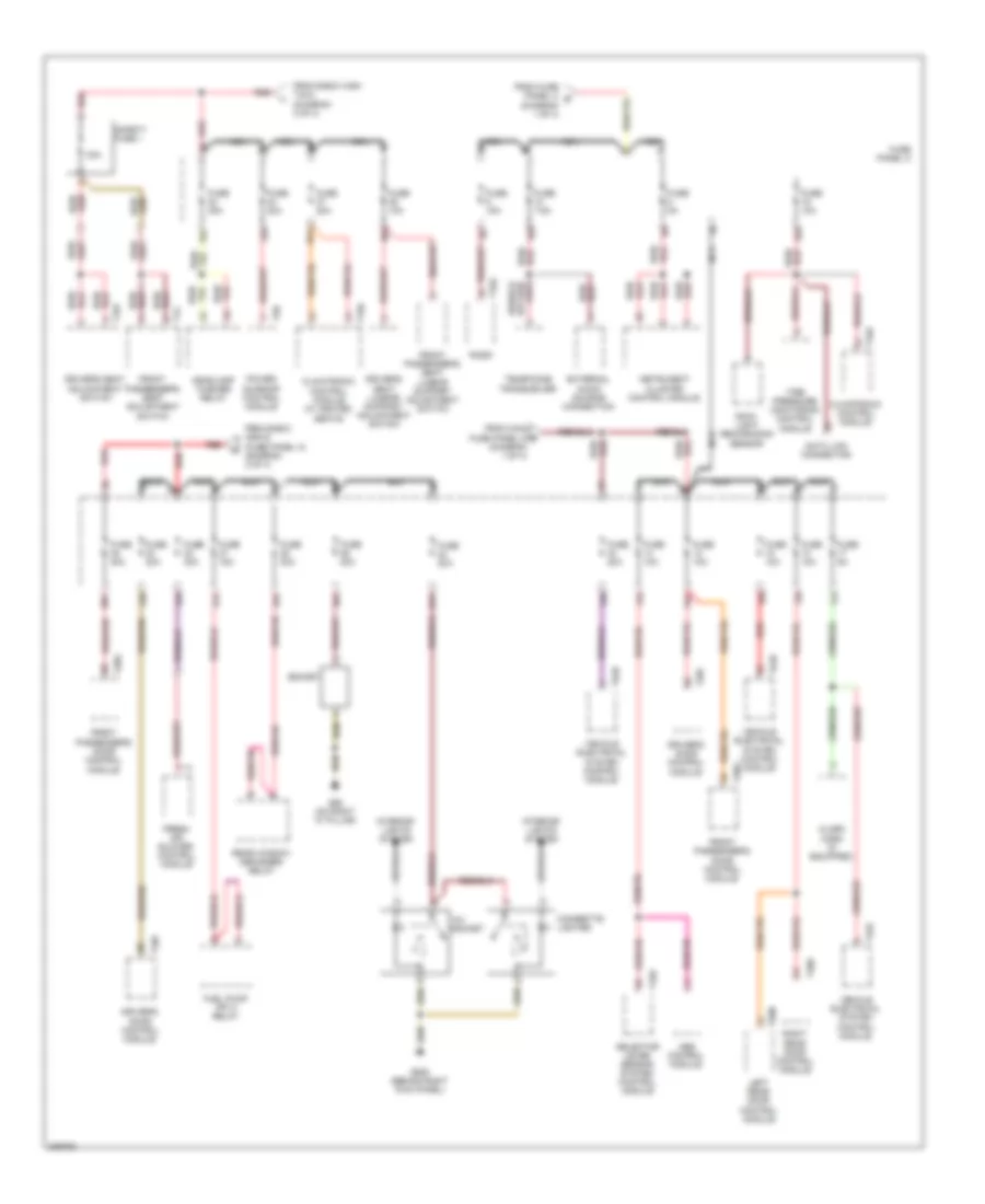
2.0L Turbo, Power Distribution Wiring Diagram, BPY Early Production (3 of 4) for Audi A3 2009
List of elements for 2.0L Turbo, Power Distribution Wiring Diagram, BPY Early Production (3 of 4) for Audi A3 2009:
- 12a
- 12v socket
- 13a
- 14a
- 15a
- 16a
- 17a
- 19a
- 22a
- 23a
- 24a
- 25a
- 26a
- 27a
- 28a
- 32a
- 33a
- 36a
- 37a
- 38a
- 43a
- Alarm horn (if equipped)
- All-wheel drive control module
- Cigarette lighter
- Climatronic control module
- Comfort system central control module
- Data link connector
- Door control module
- Driver's door control module
- Driver's seat lumbar support adjustment switch
- Fresh air blower control module
- From fuse panel a (diagram 2 of 4)
- From fuse panel c (diagram 3 of 4)
- From safety fuse 1 (diagram 2 of 4)
- Front passenger's door control module
- Front passenger's seat lumbar support adjustment switch
- Fuel pump (fp) control module
- Fuse 10a
- Fuse 15a
- Fuse 20a
- Fuse 30a
- Fuse 40a
- Fuse 5a
- Fuse panel c
- G62 (on right "c" pillar)
- G638 (behind right kick panel)
- Headlamp washer relay
- Interior lights system
- Left rear door control module
- Manual seats
- Power seats
- Power sunroof control module
- Rain/light recognition sensor
- Red
- Right rear door control module
- Selector lever sensor system control module
- Socket
- T10b
- T10d
- T10k
- T16d
- T18
- T20f
- T20g
- T20n
- T20o
- T20q
- T6b
- T6m
- T6n
- T84
- Tire pressure monitoring control module
- To fuse panel b (diagram 4 of 4)
- To fuse panel c (diagram 3 of 4)
- Vehicle electrical system control module
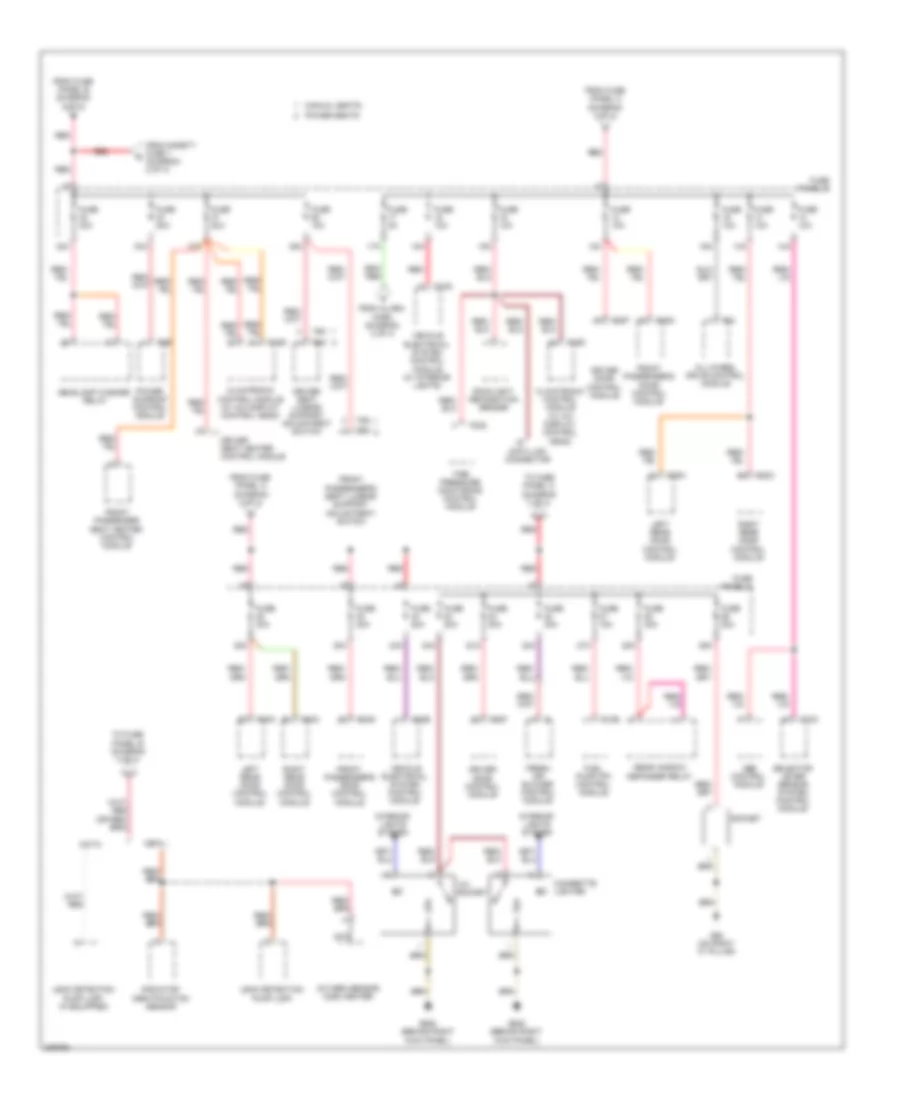
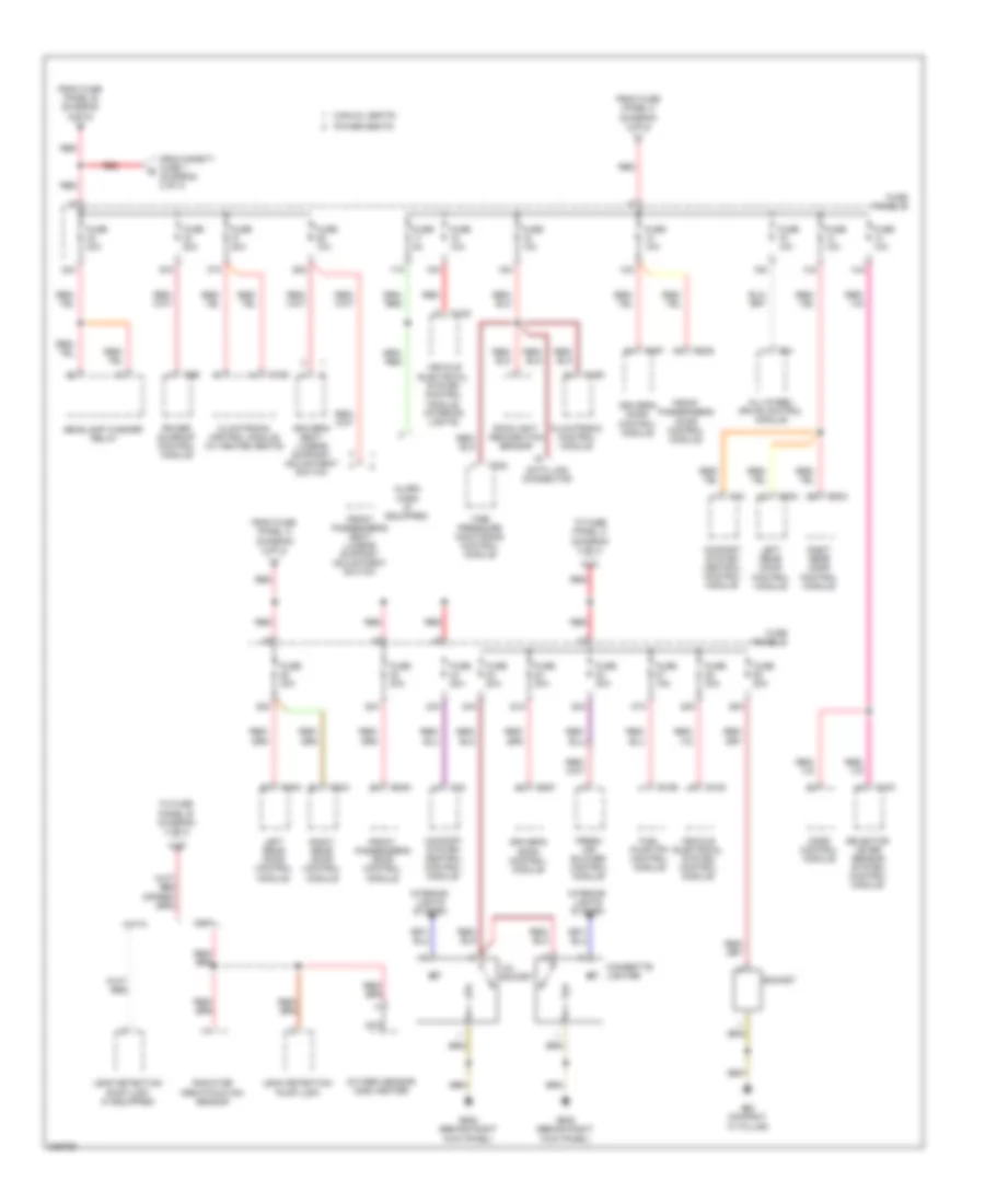
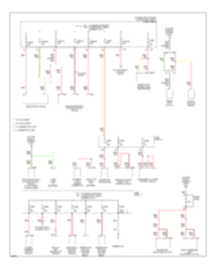
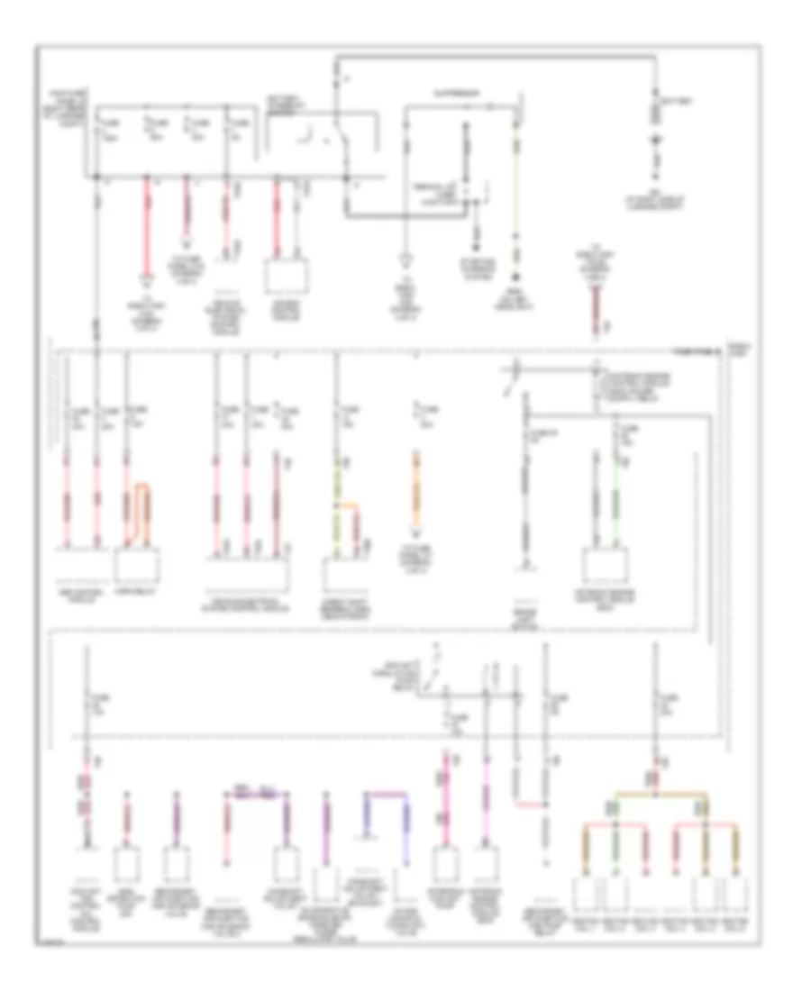
2.0L Turbo, Power Distribution Wiring Diagram, BPY Early Production (4 of 4) for Audi A3 2009
List of elements for 2.0L Turbo, Power Distribution Wiring Diagram, BPY Early Production (4 of 4) for Audi A3 2009:
- (integrated in engine compartment e-box) fuse panel b
- A/30
- Amplifier or amplifier/ woofer
- Battery
- Camshaft adjustment valve 1
- Clutch position sensor (m/t)
- Coolant circulation pump relay
- Coolant fan control module
- Data bus on board diagnostic interface
- From fuse 15 b (diagram 2 of 4)
- From fuse 28 (diagram 2 of 4)
- From fuse 3 (diagram 2 of 4)
- From fuse 9 c (diagram 2 of 4)
- From fuse panel c (diagram 3 of 4)
- From secondary air injection pump relay (diagram 4 of 4)
- Fuse 1 fuse 16 30a
- Fuse 1 fuse 3 40a
- Fuse 15a
- Fuse 16 fuse 2 5a
- Fuse 17 fuse 6 5a
- Fuse 19 fuse 8 15a
- Fuse 20 fuse 9 5a
- Fuse 23 10a
- Fuse 24 fuse 12 5a
- Fuse 29 5a
- Fuse 30a
- Fuse 31 fuse 19 30a
- Fuse 38 10a
- Fuse 39 5a
- Fuse 4 fuse 3 5a
- Fuse 40 20a
- Fuse 47 fuse 26 30a
- Fuse 5 fuse 17 15a
- Fuse 52 fuse 30 50a
- Fuse 53 fuse 29 50a
- Fuse 5a
- Fuse 9 15a
- Fuse panel c
- G12 (left side of engine compt)
- Ignition coil 1
- Ignition coil 2
- Ignition coil 3
- Ignition coil 4
- Instrument cluster control module
- L/30
- M/30
- Motronic engine control module
- Motronic engine control module (ecm)
- Nca
- Radio/navigation display unit control module
- Red
- Satellite radio (if equipped)
- Secondary air injection pump relay
- Starting/charging system
- Steering column electronic systems control module
- T11b
- T11c
- T16g
- T20b
- T20d
- T26
- T2t
- T32
- T40
- T6h
- T8h
- T8u
- T94
- Telephone transceiver
- To fuse 28 (diagram 4 of 4)
- Vehicle electrical system control module
- W/ high e-box
- W/ low e-box
- W/ woofer
- W/o woofer
- Wiper motor control module
2.0L Turbo, Power Distribution Wiring Diagram, BPY Late Production (1 of 4) for Audi A3 2009
List of elements for 2.0L Turbo, Power Distribution Wiring Diagram, BPY Late Production (1 of 4) for Audi A3 2009:
- Abs control module
- After-run coolant pump
- Air bag control module
- Battery
- Battery interrupt igniter
- Brake light switch
- Camshaft adjustment valve 1
- Clutch position sensor
- Coolant circulation pump relay
- Coolant fan control (fc) control module
- Direct shift gearbox (dsg) mechatronic
- E-box high
- Evaporative emission (evap) canister purge regulator valve
- Fuse
- Fuse 10a
- Fuse 125a
- Fuse 15a
- Fuse 20a
- Fuse 30a
- Fuse 39 5a
- Fuse 40a
- Fuse 5a
- Fuse 80a
- Fuse panel b
- G51 (at right side of luggage compt)
- G655 (on left headlight)
- Horn relay
- Ignition coil 1 w/ power output stage
- Ignition coil 2 w/ power output stage
- Ignition coil 3 w/ power output stage
- Ignition coil 4 w/ power output stage
- Intake manifold tuning (imt) valve
- L/30
- M/t
- Main fuse panel d (right rear of luggage compt)
- Motronic engine control module (ecm)
- Nca
- Red
- Starting/ charging system
- Suppressor
- T20e
- T26
- T2aa
- T2ab
- T2t
- T40
- T52a
- T52c
- T94
- Terminal 30 wire junction
- To e-box high a/30 (diagram 2 of 4)
- To e-box high m/30 (diagram 2 of 4)
- To e-box high t26-5 (diagram 2 of 4)
- To e-box high t40-28 (diagram 2 of 4)
- To fuse panel c-10 (diagram 4 of 4)
- To fuse panel c-43 (diagram 4 of 4)
- Vehicle electrical system control module
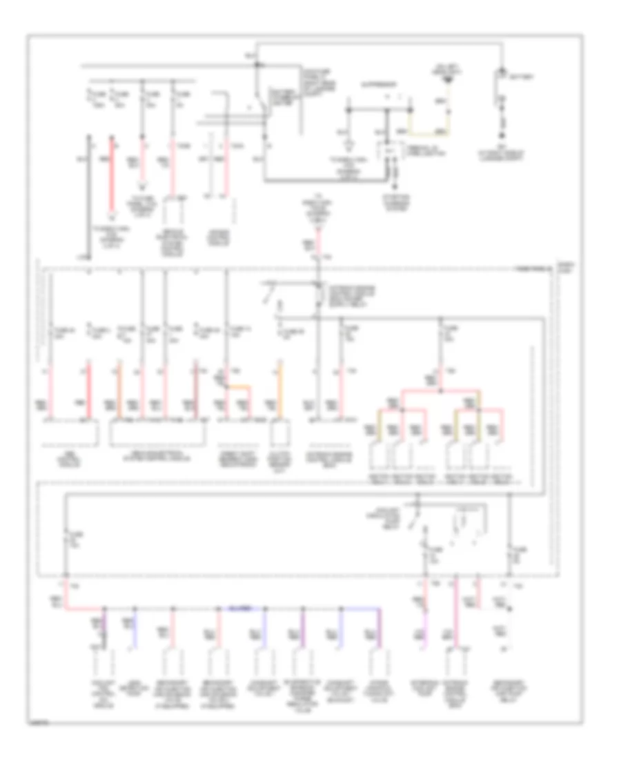
2.0L Turbo, Power Distribution Wiring Diagram, BPY Late Production (2 of 4) for Audi A3 2009
List of elements for 2.0L Turbo, Power Distribution Wiring Diagram, BPY Late Production (2 of 4) for Audi A3 2009:
- 200a
- A/30
- Amplifier
- Amplifier/ woofer
- Coolant fan control (fc) module
- Data bus on board diagnostic interface
- E-box high
- Electronic damping control module
- Evaporative emission (evap) canister purge regulator valve
- From e-box high t26-13 (diagram 1 of 4)
- From e-box high t40-15 (diagram 1 of 4)
- From main fuse panel d (diagram 1 of 4)
- From suppressor (diagram 1 of 4)
- Fuel pressure regulator valve
- Fuse 10a
- Fuse 150a
- Fuse 15a
- Fuse 17 5a
- Fuse 30a
- Fuse 50a
- Fuse 5a
- Fuse 80a
- Fuse panel a
- Fuse panel b
- Leak detection pimp (ldp)
- M/30
- Motronic engine control module (ecm)
- Nca
- Oxygen sensor (o2s) 1 heater
- Oxygen sensor (o2s) heater
- Power steering control module
- Red
- Starting/ charging system
- Steering column electronic systems control module
- T20b
- T26
- T2a
- T40
- T4d
- T94
- To fuse panel c-22 (diagram 4 of 4)
- To fuse panel c-32 (diagram 4 of 4)
- Turbocharger recirculating valve
- W/ generator 140a
- W/o generator 140a
- Wastegate bypass regulator valve
- Wiper motor control module
2.0L Turbo, Power Distribution Wiring Diagram, BPY Late Production (3 of 4) for Audi A3 2009
List of elements for 2.0L Turbo, Power Distribution Wiring Diagram, BPY Late Production (3 of 4) for Audi A3 2009:
- 19a
- 20a
- 40a
- 41a
- 47a
- A/c control module
- Abs control module
- Air bag control module
- Air quality sensor
- All wheel drive control module
- Asr/esp button
- Automatic day/night interior mirror
- Climatronic control module
- Data bus on board diagnostic interface
- Data link connector
- Direct shift gearbox (dsg) mechatronic
- Driver seat heater control module
- Electronic damping control module
- From e-box high t40-3 (diagram 2 of 4)
- Front passenger seat heater control module
- Front passenger's air bag disabled indicator lamp
- Fuel pump (fp) control module
- Fuse 10a
- Fuse 15a
- Fuse 19 10a
- Fuse 20 5a
- Fuse 40a
- Fuse 5a
- Fuse panel c
- G44 (behind left kick panel)
- Garage door opener control head
- Garage door opener control module
- Headlamp range control module
- Heater control module
- High pressure sensor
- Left headlamp power output stage
- Left headlight assembly
- Left washer nozzle heater (if equipped)
- Mass air flow (maf) sensor
- Motronic engine control module (ecm)
- Nca
- Oil level thermal sensor
- Parking aid control module
- Positive crankcase ventilation (pcv) heating element (if equipped)
- Power steering control module
- Rear window wiper motor
- Red
- Red/
- Right headlamp power output stage
- Right headlight assembly
- Right washer nozzle heater (if equipped)
- Seat occupied recognition control module
- Selector lever sensor system control module
- Starting/ charging system
- T10k
- T16d
- T16f
- T20e
- T26a
- T3w
- T52b
- T8y
- T94
- Telephone amplifier
- Vehicle electrical system control module
2.0L Turbo, Power Distribution Wiring Diagram, BPY Late Production (4 of 4) for Audi A3 2009
List of elements for 2.0L Turbo, Power Distribution Wiring Diagram, BPY Late Production (4 of 4) for Audi A3 2009:
- (diagram 1 of 4)
- 10a
- 12a
- 12v socket
- 13a
- 14a
- 15a
- 16a
- 17a
- 22a
- 23a
- 24a
- 25a
- 26a
- 27a
- 30a
- 32a
- 33a
- 36a
- 37a
- 38a
- 43a
- Alarm horn (if equipped)
- Cigarette lighter
- Climatronic control module
- Climatronic control module (w/ heated seats)
- Data link connector
- Driver's door control module
- Driver's seat adjustment switch
- Driver's seat lumbar support adjustment switch
- External audio source transceiver connection
- Fresh air blower control module
- From e-box high t40-2 (diagram 2 of 4)
- From e-box high-d (fuse panel a) (diagram 2 of 4)
- From fuse panel c e
- From main fuse panel d (diagram 1 of 4)
- Front passenger's door control module
- Front passenger's seat adjustment switch
- Front passenger's seat lumbar support adjustment switch
- Fuel pump (fp) control module
- Fuse 10a
- Fuse 15a
- Fuse 20a
- Fuse 30a
- Fuse 40a
- Fuse 5a
- Fuse 7.5a
- Fuse panel c
- G62 (on right "c" pillar)
- G638 (behind right kick panel)
- Headlamp washer relay
- Instrument cluster control module
- Interior lights system
- Left rear door control module
- Nca
- Power sunroof control module
- Radio
- Rain/ light recognition sensor
- Rear window defogger relay
- Red
- Right rear door control module
- Safety fuse 1
- Satellite radio
- Selector lever sensor system control module
- Socket
- T10k
- T16d
- T16g
- T20f
- T20g
- T20n
- T20o
- T4w
- T4x
- T52b
- T52c
- T6b
- T8v
- Telephone
- Tire pressure monitoring control module
- Vehicle electrical system control module
2.0L Turbo, Power Distribution Wiring Diagram, CBFA Early Production (1 of 4) for Audi A3 2009
List of elements for 2.0L Turbo, Power Distribution Wiring Diagram, CBFA Early Production (1 of 4) for Audi A3 2009:
- 18a
- 20a
- 41a
- 42a
- Abs control module
- Air bag control module
- Air quality sensor
- Asr/esp button
- Automatic day/night interior mirror
- Backup light switch (m/t)
- Brake light switch
- Cbfa
- Ccta
- Climatronic control module
- Data bus on board diagnostic interface
- Data link connector
- Direct shift gearbox (dsg) mechatronic
- Ecm (cbfa)
- Electronic damping control module
- Engine control module (ecm)
- Front passenger's air bag disabled indicator lamp
- Fuel pump (fp) control module
- Fuse 10a
- Fuse 15a
- Fuse 20 5a
- Fuse 40a
- Fuse 5a
- Fuse panel c
- G44 (behind left kick panel)
- Garage door opener control head
- Garage door opener control module
- Headlamp range control module
- High pressure sensor
- Left headlamp power assembly
- Left headlamp power output stage
- Left washer nozzle heater (if equipped)
- Light switch
- Load reduction relay
- Mass air flow sensor
- Oil level thermal sensor (if equipped)
- Parking aid control module
- Power steering control module
- Rear window wiper motor
- Red
- Right headlamp power assembly
- Right headlamp power output stage
- Right washer nozzle heater (if equipped)
- Seat occupied recognition control module
- Selector lever sensor system control module
- Solid state
- Starting/ charging system
- T100a
- T10b
- T10e
- T10k
- T11b
- T14c
- T14d
- T16d
- T16f
- T20d
- T20e
- T26b
- T2t
- T3w
- T47
- T6h
- T8h
- T94
- Tire pressure monitring button
- Vehicle electrical system control module
2.0L Turbo, Power Distribution Wiring Diagram, CBFA Early Production (2 of 4) for Audi A3 2009
List of elements for 2.0L Turbo, Power Distribution Wiring Diagram, CBFA Early Production (2 of 4) for Audi A3 2009:
- (integrated in engine compartment e-box) fuse panel b
- 30a
- Abs control module
- Amplifier
- Amplifier/ woofer
- Coolant fan control (fc) module
- Direct shift gearbox (dsg) mechatronic
- Driver's seat adjustment switch
- Electronic damping control module
- Front passenger's seat adjustment switch
- Fuse 1 30a
- Fuse 150a 200a
- Fuse 17 5a
- Fuse 18 30a
- Fuse 19 30a
- Fuse 2 5a
- Fuse 25 40a
- Fuse 26 30a
- Fuse 28 40a
- Fuse 29 40a
- Fuse 30a
- Fuse 4 20a
- Fuse 40a
- Fuse 5 15a
- Fuse 50a
- Fuse 80a
- Fuse 9 5a
- Fuse panel a
- Generator
- Nca
- Power steering control module
- Preheating coolant high heat output relay
- Preheating coolant low heat output relay
- Red
- Safety fuse 1
- Satellite radio (if equipped)
- Steering column electronic systems control
- T11b
- T11c
- T16h
- T20b
- T20e
- T2a
- T2t
- T40
- T47
- T4w
- T4x
- T8u
- To fuse 32 (diagram 3 of 4)
- To fuse panel c (diagram 3 of 4)
- Vehicle electrical system control module
- W/ hold assist
- W/o hold assist
- Wiper motor control module
2.0L Turbo, Power Distribution Wiring Diagram, CBFA Early Production (3 of 4) for Audi A3 2009
List of elements for 2.0L Turbo, Power Distribution Wiring Diagram, CBFA Early Production (3 of 4) for Audi A3 2009:
- 12a
- 12v socket
- 13a
- 14a
- 15a
- 16a
- 17a
- 19a
- 22a
- 23a
- 24a
- 25a
- 26a
- 27a
- 28a
- 32a
- 33a
- 36a
- 37a
- 38a
- 43a
- Alarm horn (if equipped)
- All-wheel drive control module
- Cbfa
- Ccta
- Cigarette lighter
- Climatronic control module
- Climatronic control module (w/ heated seats)
- Comfort system central control module
- Data link connector
- Door control module
- Driver's door control module
- Driver's seat lumbar support adjustment switch
- Fresh air blower control module
- From fuse panel a (diagram 2 of 4)
- From fuse panel b (diagram 2 of 4)
- From fuse panel c (diagram 3 of 4)
- From safety fuse 1 (diagram 2 of 4)
- Front passenger's door control module
- Front passenger's seat lumbar support adjustment switch
- Fuel pump (fp) control module
- Fuse 10a
- Fuse 15a
- Fuse 20a
- Fuse 30a
- Fuse 40a
- Fuse 5a
- Fuse panel c
- G62 (on right "c" pillar)
- G638 (behind right kick panel)
- Headlamp washer relay
- Interior lights system
- Leak detection pump (ldp)
- Leak detection pump (ldp) (if equipped)
- Left rear door control module
- Manual seats
- Nca
- Oxygen sensor (o2s) heater
- Power seats
- Power sunroof control module
- Radiator identification sensor
- Rain/light recognition sensor
- Red
- Right rear door control module
- Selector lever sensor system control module
- Socket
- T10b
- T10d
- T10k
- T16d
- T18
- T20f
- T20g
- T20n
- T20o
- T20q
- T6b
- T84
- Tire pressure monitoring control module
- To fuse panel b (diagram 4 of 4)
- To fuse panel c (diagram 3 of 4)
- Vehicle electrical system control module
- Vehicle electrical system control module (interior lights)
2.0L Turbo, Power Distribution Wiring Diagram, CBFA Early Production (4 of 4) for Audi A3 2009
List of elements for 2.0L Turbo, Power Distribution Wiring Diagram, CBFA Early Production (4 of 4) for Audi A3 2009:
- (integrated in engine compartment e-box) fuse panel b
- (not used)
- Battery
- Camshaft adjustment valve 1
- Cbfa
- Ccta
- Clutch position sensor (m/t)
- Coolant circulation pump relay
- Coolant circulation pump relay (cbfa)
- Coolant fan control (fc) module
- Data bus on board diagnostic interface
- Engine control module (ecm)
- Evaporative emission (evap) canister purge regulator valve
- From coolant circulation pump relay (diagram 4 of 4)
- From fuse 15 (diagram 4 of 4)
- From fuse 3 (diagram 2 of 4)
- From fuse 49 & 28 (diagram 2 of 4)
- From fuse 6 j (diagram 4 of 4)
- From leak detection pump (ldp) (diagram 3 of 4)
- Fuel pressure regulator valve
- Fuse 10 10a
- Fuse 13 15a
- Fuse 14 20a
- Fuse 15 10a
- Fuse 2 20a (cbfa)
- Fuse 20 20a
- Fuse 21 10a
- Fuse 22 5a
- Fuse 23 5a
- Fuse 24 10a
- Fuse 50a
- Fuse 5a
- G12 (left side of engine compt)
- Ignition coil 1 w/ power output stage
- Ignition coil 2 w/ power output stage
- Ignition coil 3 w/ power output stage
- Ignition coil 4 w/ power output stage
- Instrument cluster control module
- Intake manifold runner control (imrc) valve
- Nca
- Oxygen sensor (o2s) 1 heater
- Oxygen sensor (o2s) heater (ccta) oxygen sensor (o2s) 3 heater (cbfa)
- Red
- Secondary air injection (air) pump relay
- Secondary air injection (air) solenoid valve (cbfa)
- Starting/charging system
- Steering column electronic systems control module
- T20b
- T20d
- T2t
- T40
- T8h
- T94
- To coolant circulation pump relay (diagram 4 of 4)
- To fuse 14 (diagram 4 of 4)
- To fuse panel b (diagram 4 of 4)
- Turbocharger recirculating valve
- Vehicle electrical system control module
- Wastegate bypass regulator valve
2.0L Turbo, Power Distribution Wiring Diagram, CBFA Late Production (1 of 4) for Audi A3 2009
List of elements for 2.0L Turbo, Power Distribution Wiring Diagram, CBFA Late Production (1 of 4) for Audi A3 2009:
- 18a
- 20a
- 40a
- 41a
- 47a
- A/c control module
- Abs control module
- Air bag control module
- Air quality sensor
- Asr/esp button
- Automatic day/night interior mirror
- Backup light switch (m/t)
- Brake light switch
- Cbfa
- Climatronic control module (w/ a/c display control head)
- Data bus on board diagnostic interface
- Data link connector
- Direct shift gearbox (dsg) mechatronic
- Driver seat heater control module
- Electronic damping control module
- Engine control module (ecm)
- Engine control module (ecm) (cbfa)
- Front passenger seat heater module
- Front passenger's air bag disabled indicator lamp
- Fuel pump (fp) control module
- Fuse 10a
- Fuse 15a
- Fuse 20 5a
- Fuse 40a
- Fuse 5 5a
- Fuse 5a
- Fuse 6 5a
- Fuse panel c
- G44 (behind left kick panel)
- Garage door opener control head
- Garage door opener control module
- Headlamp range control module
- Heater control module
- High pressure sensor
- Left headlamp power assembly
- Left headlamp power output stage
- Left washer nozzle heater (if equipped)
- Light switch
- Mass air flow (maf) sensor
- Oil level thermal sensor (if equipped)
- Parking aid control module
- Positive crankcase ventilation (pcv) heating element (if equipped)
- Power steering control module
- Rear window wiper motor
- Red
- Right headlamp power assembly
- Right headlamp power output stage
- Right washer nozzle heater (if equipped)
- Seat occupied recognition control module (if equipped)
- Selector lever sensor system control module
- Starting/ charging system
- T100a
- T10b
- T10e
- T10k
- T14c
- T14d
- T16d
- T16f
- T20c
- T20d
- T20e
- T26b
- T3w
- T52b
- T52c
- T6y
- T8ad
- T94
- Telephone amplifier (w/o cellular telephone)
- Tire pressure monitoring button (if equipped)
- To fuse panel b (diagram 4 of 4)
- Vehicle electrical system control module
- Vehicle electrical system control module (cbfa)
- W/ automatic high beam control
- W/o automatic high beam control
2.0L Turbo, Power Distribution Wiring Diagram, CBFA Late Production (2 of 4) for Audi A3 2009
List of elements for 2.0L Turbo, Power Distribution Wiring Diagram, CBFA Late Production (2 of 4) for Audi A3 2009:
- (integrated in engine compartment e-box) fuse panel b
- 10a
- 30a
- A/t
- Abs control module
- Alarm horn (if equipped)
- Brake light switch
- Clutch position sensor
- Coolant fan control (fc) module
- Direct shift gearbox (dsg) mechatronic
- Driver seat adjustment switch
- Electronic damping control module
- External audio source connection
- Front passenger seat adjustment switch
- Fuse 1 40a
- Fuse 150a 200a
- Fuse 15a
- Fuse 16 30a
- Fuse 25 40a
- Fuse 26 30a
- Fuse 28 40a
- Fuse 29 40a
- Fuse 30a
- Fuse 4 20a
- Fuse 40a
- Fuse 50a
- Fuse 5a
- Fuse 7.5a
- Fuse 80a
- Fuse panel a
- Fuse panel c
- Generator
- Instrument cluster control module
- M/t
- Nca
- Power steering control module
- Preheating coolant high heat output relay
- Preheating coolant low heat output relay
- Radio/navigation display unit control module
- Red
- Safety fuse 1
- Satellite radio (if equipped)
- T16g
- T20e
- T2a
- T2t
- T40
- T47
- T4w
- T4x
- T52a
- T52c
- T8u
- Telephone transceiver
- To fuse panel b (diagram 4 of 4)
- To fuse panel c (diagram 3 of 4)
- Vehicle electrical system control module
- Vehicle electrical system control module (w/ anti-theft alarm system)
- W/ generator (140a)
- W/ hold assist
- W/o generator (140a)
- W/o hold assist
2.0L Turbo, Power Distribution Wiring Diagram, CBFA Late Production (3 of 4) for Audi A3 2009
List of elements for 2.0L Turbo, Power Distribution Wiring Diagram, CBFA Late Production (3 of 4) for Audi A3 2009:
- 12a
- 12v socket
- 13a
- 14a
- 15a
- 16a
- 17a
- 19a
- 22a
- 23a
- 24a
- 25a
- 26a
- 27a
- 28a
- 32a
- 33a
- 36a
- 37a
- 38a
- 43a
- Abs control module
- All-wheel drive control module
- Cbfa
- Ccta
- Cigarette lighter
- Climatronic control module (w/ a/c display control head)
- Data link connector
- Driver door control module
- Driver seat heater control module
- Driver seat lumbar support adjustment switch
- Fresh air blower control module
- From alarm horn (diagram 2 of 4)
- From fuse panel a (diagram 2 of 4)
- From fuse panel b (diagram 2 of 4)
- From fuse panel c (diagram 3 of 4)
- From safety fuse 1 (diagram 2 of 4)
- Front passenger seat heater control module
- Front passenger's door control module
- Front passenger's seat lumbar support adjustment switch
- Fuel pump (fp) control module
- Fuse 10a
- Fuse 15a
- Fuse 20a
- Fuse 30a
- Fuse 40a
- Fuse 5a
- Fuse panel c
- G62 (on right "c" pillar)
- G638 (behind right kick panel)
- Headlamp washer relay
- Interior lights system
- Leak detection pump (ldp)
- Leak detection pump (ldp) (if equipped)
- Left rear door control module
- Manual seats
- Nca
- Oxygen sensor (o2s) heater
- Power seats
- Power sunroof control module
- Radiator identification sensor
- Rain/light recognition sensor
- Rear window defogger relay
- Red
- Right rear door control module
- Selector lever sensor system control module
- Socket
- T10b
- T10d
- T10k
- T16d
- T20f
- T20g
- T20n
- T20o
- T20q
- T52b
- T6b
- T6m
- T6n
- T84
- Tire pressure monitoring control module
- To fuse panel b (diagram 4 of 4)
- To fuse panel c (diagram 3 of 4)
- Vehicle electrical system control module
- Vehicle electrical system control module (w/ interior lights)
2.0L Turbo, Power Distribution Wiring Diagram, CBFA Late Production (4 of 4) for Audi A3 2009
List of elements for 2.0L Turbo, Power Distribution Wiring Diagram, CBFA Late Production (4 of 4) for Audi A3 2009:
- (imrc) valve
- (integrated in engine compartment e-box) fuse panel b
- (not used)
- Amplifier
- Amplifier/ woofer
- Battery
- Camshaft adjustment valve 1
- Cbfa
- Ccta
- Coolant circulation pump relay
- Coolant circulation pump relay (cbfa)
- Coolant fan control (fc) module
- Data bus on board diagnostic interface
- Engine control module (ecm)
- Evaprative emission (evap) conister purge regulator valve
- From brake light switch (diagram 2 of 4)
- From coolant circulation pump relay (diagram 4 of 4)
- From fuse 15 (diagram 4 of 4)
- From fuse 28 (diagram 2 of 4)
- From fuse 30 l (diagram 4 of 4)
- From fuse 7 (diagram 2 of 4)
- From fuse panel b (diagram 4 of 4)
- From leak detection pump (ldp) (diagram 3 of 4)
- Fuel pressure regulator valve
- Fuse 10a
- Fuse 12 5a
- Fuse 13 15a
- Fuse 14 20a
- Fuse 15 10a
- Fuse 17 15a
- Fuse 18 30a
- Fuse 19 30a
- Fuse 2 20a (cbfa)
- Fuse 20 20a
- Fuse 21 10a
- Fuse 22 5a
- Fuse 23 5a
- Fuse 24 10a
- Fuse 3 5a
- Fuse 30 50a
- Fuse 6 5a
- G12 (left side of engine compt)
- Horn relay
- Ignition coil 1 w/ power output stage
- Ignition coil 2 w/ power output stage
- Ignition coil 3 w/ power output stage
- Ignition coil 4 w/ power output stage
- Intake manifold runner control
- M/30
- Nca
- Oxygen sensor (o2s) 1 heater
- Oxygen sensor (o2s) heater (ccta) oxygen sensor (o2s) 3 heater (cbfa)
- Red
- Secondary air injection (air) pump relay
- Secondary air injection (air) solenoid valve (cbfa)
- Starting/charging system
- Steering column electronic systems control module
- T20b
- T20d
- T40
- T52a
- T94
- To coolant circulation pump relay (diagram 4 of 4)
- To fuse 14 (diagram 4 of 4)
- Turbocharger recirculating valve
- Vehicle electrical system control module
- Wastegate bypass regulator valve
- Wiper motor control module
2.0L Turbo, Power Distribution Wiring Diagram, CCTA Early Production (1 of 4) for Audi A3 2009
List of elements for 2.0L Turbo, Power Distribution Wiring Diagram, CCTA Early Production (1 of 4) for Audi A3 2009:
- 18a
- 20a
- 41a
- 42a
- Abs control module
- Air bag control module
- Air quality sensor
- Asr/esp button
- Automatic day/night interior mirror
- Backup light switch (m/t)
- Brake light switch
- Cbfa
- Ccta
- Climatronic control module
- Data bus on board diagnostic interface
- Data link connector
- Direct shift gearbox (dsg) mechatronic
- Ecm (cbfa)
- Electronic damping control module
- Engine control module (ecm)
- Front passenger's air bag disabled indicator lamp
- Fuel pump (fp) control module
- Fuse 10a
- Fuse 15a
- Fuse 20 5a
- Fuse 40a
- Fuse 5a
- Fuse panel c
- G44 (behind left kick panel)
- Garage door opener control head
- Garage door opener control module
- Headlamp range control module
- High pressure sensor
- Left headlamp power assembly
- Left headlamp power output stage
- Left washer nozzle heater (if equipped)
- Light switch
- Load reduction relay
- Mass air flow sensor
- Oil level thermal sensor (if equipped)
- Parking aid control module
- Power steering control module
- Rear window wiper motor
- Red
- Right headlamp power assembly
- Right headlamp power output stage
- Right washer nozzle heater (if equipped)
- Seat occupied recognition control module
- Selector lever sensor system control module
- Solid state
- Starting/ charging system
- T100a
- T10b
- T10e
- T10k
- T11b
- T14c
- T14d
- T16d
- T16f
- T20d
- T20e
- T26b
- T2t
- T3w
- T47
- T6h
- T8h
- T94
- Tire pressure monitring button
- Vehicle electrical system control module
2.0L Turbo, Power Distribution Wiring Diagram, CCTA Early Production (2 of 4) for Audi A3 2009
List of elements for 2.0L Turbo, Power Distribution Wiring Diagram, CCTA Early Production (2 of 4) for Audi A3 2009:
- (integrated in engine compartment e-box) fuse panel b
- 30a
- Abs control module
- Amplifier
- Amplifier/ woofer
- Coolant fan control (fc) module
- Direct shift gearbox (dsg) mechatronic
- Driver's seat adjustment switch
- Electronic damping control module
- Front passenger's seat adjustment switch
- Fuse 1 30a
- Fuse 150a 200a
- Fuse 17 5a
- Fuse 18 30a
- Fuse 19 30a
- Fuse 2 5a
- Fuse 25 40a
- Fuse 26 30a
- Fuse 28 40a
- Fuse 29 40a
- Fuse 30a
- Fuse 4 20a
- Fuse 40a
- Fuse 5 15a
- Fuse 50a
- Fuse 80a
- Fuse 9 5a
- Fuse panel a
- Generator
- Nca
- Power steering control module
- Preheating coolant high heat output relay
- Preheating coolant low heat output relay
- Red
- Safety fuse 1
- Satellite radio (if equipped)
- Steering column electronic systems control
- T11b
- T11c
- T16h
- T20b
- T20e
- T2a
- T2t
- T40
- T47
- T4w
- T4x
- T8u
- To fuse 32 (diagram 3 of 4)
- To fuse panel c (diagram 3 of 4)
- Vehicle electrical system control module
- W/ hold assist
- W/o hold assist
- Wiper motor control module
2.0L Turbo, Power Distribution Wiring Diagram, CCTA Early Production (3 of 4) for Audi A3 2009
List of elements for 2.0L Turbo, Power Distribution Wiring Diagram, CCTA Early Production (3 of 4) for Audi A3 2009:
- 12a
- 12v socket
- 13a
- 14a
- 15a
- 16a
- 17a
- 19a
- 22a
- 23a
- 24a
- 25a
- 26a
- 27a
- 28a
- 32a
- 33a
- 36a
- 37a
- 38a
- 43a
- Alarm horn (if equipped)
- All-wheel drive control module
- Cbfa
- Ccta
- Cigarette lighter
- Climatronic control module
- Climatronic control module (w/ heated seats)
- Comfort system central control module
- Data link connector
- Door control module
- Driver's door control module
- Driver's seat lumbar support adjustment switch
- Fresh air blower control module
- From fuse panel a (diagram 2 of 4)
- From fuse panel b (diagram 2 of 4)
- From fuse panel c (diagram 3 of 4)
- From safety fuse 1 (diagram 2 of 4)
- Front passenger's door control module
- Front passenger's seat lumbar support adjustment switch
- Fuel pump (fp) control module
- Fuse 10a
- Fuse 15a
- Fuse 20a
- Fuse 30a
- Fuse 40a
- Fuse 5a
- Fuse panel c
- G62 (on right "c" pillar)
- G638 (behind right kick panel)
- Headlamp washer relay
- Interior lights system
- Leak detection pump (ldp)
- Leak detection pump (ldp) (if equipped)
- Left rear door control module
- Manual seats
- Nca
- Oxygen sensor (o2s) heater
- Power seats
- Power sunroof control module
- Radiator identification sensor
- Rain/light recognition sensor
- Red
- Right rear door control module
- Selector lever sensor system control module
- Socket
- T10b
- T10d
- T10k
- T16d
- T18
- T20f
- T20g
- T20n
- T20o
- T20q
- T6b
- T84
- Tire pressure monitoring control module
- To fuse panel b (diagram 4 of 4)
- To fuse panel c (diagram 3 of 4)
- Vehicle electrical system control module
- Vehicle electrical system control module (interior lights)
2.0L Turbo, Power Distribution Wiring Diagram, CCTA Early Production (4 of 4) for Audi A3 2009
List of elements for 2.0L Turbo, Power Distribution Wiring Diagram, CCTA Early Production (4 of 4) for Audi A3 2009:
- (integrated in engine compartment e-box) fuse panel b
- (not used)
- Battery
- Camshaft adjustment valve 1
- Cbfa
- Ccta
- Clutch position sensor (m/t)
- Coolant circulation pump relay
- Coolant circulation pump relay (cbfa)
- Coolant fan control (fc) module
- Data bus on board diagnostic interface
- Engine control module (ecm)
- Evaporative emission (evap) canister purge regulator valve
- From coolant circulation pump relay (diagram 4 of 4)
- From fuse 15 (diagram 4 of 4)
- From fuse 3 (diagram 2 of 4)
- From fuse 49 & 28 (diagram 2 of 4)
- From fuse 6 j (diagram 4 of 4)
- From leak detection pump (ldp) (diagram 3 of 4)
- Fuel pressure regulator valve
- Fuse 10 10a
- Fuse 13 15a
- Fuse 14 20a
- Fuse 15 10a
- Fuse 2 20a (cbfa)
- Fuse 20 20a
- Fuse 21 10a
- Fuse 22 5a
- Fuse 23 5a
- Fuse 24 10a
- Fuse 50a
- Fuse 5a
- G12 (left side of engine compt)
- Ignition coil 1 w/ power output stage
- Ignition coil 2 w/ power output stage
- Ignition coil 3 w/ power output stage
- Ignition coil 4 w/ power output stage
- Instrument cluster control module
- Intake manifold runner control (imrc) valve
- Nca
- Oxygen sensor (o2s) 1 heater
- Oxygen sensor (o2s) heater (ccta) oxygen sensor (o2s) 3 heater (cbfa)
- Red
- Secondary air injection (air) pump relay
- Secondary air injection (air) solenoid valve (cbfa)
- Starting/charging system
- Steering column electronic systems control module
- T20b
- T20d
- T2t
- T40
- T8h
- T94
- To coolant circulation pump relay (diagram 4 of 4)
- To fuse 14 (diagram 4 of 4)
- To fuse panel b (diagram 4 of 4)
- Turbocharger recirculating valve
- Vehicle electrical system control module
- Wastegate bypass regulator valve
2.0L Turbo, Power Distribution Wiring Diagram, CCTA Late Production (1 of 4) for Audi A3 2009
List of elements for 2.0L Turbo, Power Distribution Wiring Diagram, CCTA Late Production (1 of 4) for Audi A3 2009:
- 18a
- 20a
- 40a
- 41a
- 47a
- A/c control module
- Abs control module
- Air bag control module
- Air quality sensor
- Asr/esp button
- Automatic day/night interior mirror
- Backup light switch (m/t)
- Brake light switch
- Cbfa
- Climatronic control module (w/ a/c display control head)
- Data bus on board diagnostic interface
- Data link connector
- Direct shift gearbox (dsg) mechatronic
- Driver seat heater control module
- Electronic damping control module
- Engine control module (ecm)
- Engine control module (ecm) (cbfa)
- Front passenger seat heater module
- Front passenger's air bag disabled indicator lamp
- Fuel pump (fp) control module
- Fuse 10a
- Fuse 15a
- Fuse 20 5a
- Fuse 40a
- Fuse 5 5a
- Fuse 5a
- Fuse 6 5a
- Fuse panel c
- G44 (behind left kick panel)
- Garage door opener control head
- Garage door opener control module
- Headlamp range control module
- Heater control module
- High pressure sensor
- Left headlamp power assembly
- Left headlamp power output stage
- Left washer nozzle heater (if equipped)
- Light switch
- Mass air flow (maf) sensor
- Oil level thermal sensor (if equipped)
- Parking aid control module
- Positive crankcase ventilation (pcv) heating element (if equipped)
- Power steering control module
- Rear window wiper motor
- Red
- Right headlamp power assembly
- Right headlamp power output stage
- Right washer nozzle heater (if equipped)
- Seat occupied recognition control module (if equipped)
- Selector lever sensor system control module
- Starting/ charging system
- T100a
- T10b
- T10e
- T10k
- T14c
- T14d
- T16d
- T16f
- T20c
- T20d
- T20e
- T26b
- T3w
- T52b
- T52c
- T6y
- T8ad
- T94
- Telephone amplifier (w/o cellular telephone)
- Tire pressure monitoring button (if equipped)
- To fuse panel b (diagram 4 of 4)
- Vehicle electrical system control module
- Vehicle electrical system control module (cbfa)
- W/ automatic high beam control
- W/o automatic high beam control
2.0L Turbo, Power Distribution Wiring Diagram, CCTA Late Production (2 of 4) for Audi A3 2009
List of elements for 2.0L Turbo, Power Distribution Wiring Diagram, CCTA Late Production (2 of 4) for Audi A3 2009:
- (integrated in engine compartment e-box) fuse panel b
- 10a
- 30a
- A/t
- Abs control module
- Alarm horn (if equipped)
- Brake light switch
- Clutch position sensor
- Coolant fan control (fc) module
- Direct shift gearbox (dsg) mechatronic
- Driver seat adjustment switch
- Electronic damping control module
- External audio source connection
- Front passenger seat adjustment switch
- Fuse 1 40a
- Fuse 150a 200a
- Fuse 15a
- Fuse 16 30a
- Fuse 25 40a
- Fuse 26 30a
- Fuse 28 40a
- Fuse 29 40a
- Fuse 30a
- Fuse 4 20a
- Fuse 40a
- Fuse 50a
- Fuse 5a
- Fuse 7.5a
- Fuse 80a
- Fuse panel a
- Fuse panel c
- Generator
- Instrument cluster control module
- M/t
- Nca
- Power steering control module
- Preheating coolant high heat output relay
- Preheating coolant low heat output relay
- Radio/navigation display unit control module
- Red
- Safety fuse 1
- Satellite radio (if equipped)
- T16g
- T20e
- T2a
- T2t
- T40
- T47
- T4w
- T4x
- T52a
- T52c
- T8u
- Telephone transceiver
- To fuse panel b (diagram 4 of 4)
- To fuse panel c (diagram 3 of 4)
- Vehicle electrical system control module
- Vehicle electrical system control module (w/ anti-theft alarm system)
- W/ generator (140a)
- W/ hold assist
- W/o generator (140a)
- W/o hold assist
2.0L Turbo, Power Distribution Wiring Diagram, CCTA Late Production (3 of 4) for Audi A3 2009
List of elements for 2.0L Turbo, Power Distribution Wiring Diagram, CCTA Late Production (3 of 4) for Audi A3 2009:
- 12a
- 12v socket
- 13a
- 14a
- 15a
- 16a
- 17a
- 19a
- 22a
- 23a
- 24a
- 25a
- 26a
- 27a
- 28a
- 32a
- 33a
- 36a
- 37a
- 38a
- 43a
- Abs control module
- All-wheel drive control module
- Cbfa
- Ccta
- Cigarette lighter
- Climatronic control module (w/ a/c display control head)
- Data link connector
- Driver door control module
- Driver seat heater control module
- Driver seat lumbar support adjustment switch
- Fresh air blower control module
- From alarm horn (diagram 2 of 4)
- From fuse panel a (diagram 2 of 4)
- From fuse panel b (diagram 2 of 4)
- From fuse panel c (diagram 3 of 4)
- From safety fuse 1 (diagram 2 of 4)
- Front passenger seat heater control module
- Front passenger's door control module
- Front passenger's seat lumbar support adjustment switch
- Fuel pump (fp) control module
- Fuse 10a
- Fuse 15a
- Fuse 20a
- Fuse 30a
- Fuse 40a
- Fuse 5a
- Fuse panel c
- G62 (on right "c" pillar)
- G638 (behind right kick panel)
- Headlamp washer relay
- Interior lights system
- Leak detection pump (ldp)
- Leak detection pump (ldp) (if equipped)
- Left rear door control module
- Manual seats
- Nca
- Oxygen sensor (o2s) heater
- Power seats
- Power sunroof control module
- Radiator identification sensor
- Rain/light recognition sensor
- Rear window defogger relay
- Red
- Right rear door control module
- Selector lever sensor system control module
- Socket
- T10b
- T10d
- T10k
- T16d
- T20f
- T20g
- T20n
- T20o
- T20q
- T52b
- T6b
- T6m
- T6n
- T84
- Tire pressure monitoring control module
- To fuse panel b (diagram 4 of 4)
- To fuse panel c (diagram 3 of 4)
- Vehicle electrical system control module
- Vehicle electrical system control module (w/ interior lights)
2.0L Turbo, Power Distribution Wiring Diagram, CCTA Late Production (4 of 4) for Audi A3 2009
List of elements for 2.0L Turbo, Power Distribution Wiring Diagram, CCTA Late Production (4 of 4) for Audi A3 2009:
- (imrc) valve
- (integrated in engine compartment e-box) fuse panel b
- (not used)
- Amplifier
- Amplifier/ woofer
- Battery
- Camshaft adjustment valve 1
- Cbfa
- Ccta
- Coolant circulation pump relay
- Coolant circulation pump relay (cbfa)
- Coolant fan control (fc) module
- Data bus on board diagnostic interface
- Engine control module (ecm)
- Evaprative emission (evap) conister purge regulator valve
- From brake light switch (diagram 2 of 4)
- From coolant circulation pump relay (diagram 4 of 4)
- From fuse 15 (diagram 4 of 4)
- From fuse 28 (diagram 2 of 4)
- From fuse 30 l (diagram 4 of 4)
- From fuse 7 (diagram 2 of 4)
- From fuse panel b (diagram 4 of 4)
- From leak detection pump (ldp) (diagram 3 of 4)
- Fuel pressure regulator valve
- Fuse 10a
- Fuse 12 5a
- Fuse 13 15a
- Fuse 14 20a
- Fuse 15 10a
- Fuse 17 15a
- Fuse 18 30a
- Fuse 19 30a
- Fuse 2 20a (cbfa)
- Fuse 20 20a
- Fuse 21 10a
- Fuse 22 5a
- Fuse 23 5a
- Fuse 24 10a
- Fuse 3 5a
- Fuse 30 50a
- Fuse 6 5a
- G12 (left side of engine compt)
- Horn relay
- Ignition coil 1 w/ power output stage
- Ignition coil 2 w/ power output stage
- Ignition coil 3 w/ power output stage
- Ignition coil 4 w/ power output stage
- Intake manifold runner control
- M/30
- Nca
- Oxygen sensor (o2s) 1 heater
- Oxygen sensor (o2s) heater (ccta) oxygen sensor (o2s) 3 heater (cbfa)
- Red
- Secondary air injection (air) pump relay
- Secondary air injection (air) solenoid valve (cbfa)
- Starting/charging system
- Steering column electronic systems control module
- T20b
- T20d
- T40
- T52a
- T94
- To coolant circulation pump relay (diagram 4 of 4)
- To fuse 14 (diagram 4 of 4)
- Turbocharger recirculating valve
- Vehicle electrical system control module
- Wastegate bypass regulator valve
- Wiper motor control module
3.2L
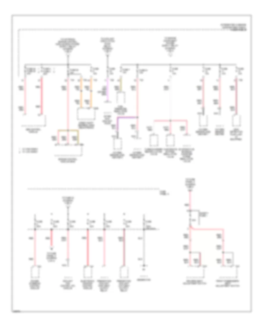
3.2L, Power Distribution Wiring Diagram, Early Production (1 of 4) for Audi A3 2009
List of elements for 3.2L, Power Distribution Wiring Diagram, Early Production (1 of 4) for Audi A3 2009:
- (on left headlight) g655
- Abs control module
- After-run coolant pump
- Air bag control module
- Battery
- Battery interrupt igniter
- Camshaft adjustment valve 1
- Camshaft adjustment valve 1 (exhaust)
- Clutch position sensor (m/t)
- Coolant circulation pump relay
- Coolant fan control (fc) module
- Direct shift gearbox (dsg) mechatronic
- E-box high
- Evaporative emission canister purge regulator valve
- Fuse 10a
- Fuse 125a
- Fuse 13 15a
- Fuse 15a
- Fuse 2 20a
- Fuse 30a
- Fuse 39 5a
- Fuse 48 40a
- Fuse 49 40a
- Fuse 5a
- Fuse 80a
- Fuse panel b
- G51 (at right side of luggage compt)
- Ignition coil 1
- Ignition coil 2
- Ignition coil 3
- Ignition coil 4
- Ignition coil 5
- Ignition coil 6
- Intake manifold tuning (imt) valve
- L/30
- Leak detection pump
- Main fuse panel d (right rear of luggage compt)
- Motronic engine control module (ecm)
- Nca
- Red
- Secondary air injection (air) pump relay
- Secondary air injection (air) solenoid valve (if equipped)
- Secondary air injection (air) solenoid valve 2 (if equipped)
- Starting/ charging system
- Suppressor
- T11b
- T11c
- T121
- T20e
- T26
- T2aa
- T2ab
- T2t
- T40
- T6h
- T8h
- Terminal 30 wire junction
- To e-box high, a/30 (diagram 2 of 4)
- To e-box high, m/30 (diagram 2 of 4)
- To e-box high, t40-28 (diagram 2 of 4)
- To fuse panel, c-43 (diagram 4 of 4)
- Vehicle electrical system control module
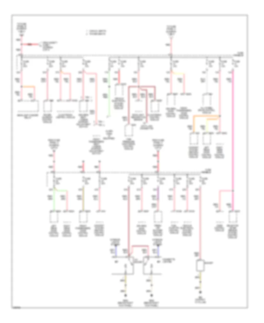
3.2L, Power Distribution Wiring Diagram, Early Production (2 of 4) for Audi A3 2009
List of elements for 3.2L, Power Distribution Wiring Diagram, Early Production (2 of 4) for Audi A3 2009:
- A/30
- Amplifier or amplifier/ woofer
- Coolant fan control (fc) module
- Cylinder 1 fuel injector
- Cylinder 2 fuel injector
- Cylinder 3 fuel injector
- Cylinder 4 fuel injector
- Cylinder 5 fuel injector
- Cylinder 6 fuel injector
- Data bus on board diagnostic interface
- E-box high
- From e-box high, t40-15 (diagram 1 of 4)
- From main fuse panel d (diagram 1 of 4)
- From suppressor (diagram 1 of 4)
- Fuel pump (fp) 2 relay
- Fuel pump (fp) relay
- Fuse 10a
- Fuse 15a
- Fuse 16 5a
- Fuse 17 5a
- Fuse 19 15a
- Fuse 20 5a
- Fuse 200a
- Fuse 24 5a
- Fuse 30a
- Fuse 31 30a
- Fuse 40a
- Fuse 49 40a
- Fuse 50a
- Fuse 53 50a
- Fuse 80a
- Fuse panel a
- Fuse panel b
- Instrument cluster control module
- M/30
- Mass air flow (maf) sensor
- Motronic engine control module
- Motronic engine control module (ecm)
- Nca
- Oxygen sensor (o2s) 1 heater
- Oxygen sensor (o2s) 2 heater
- Oxygen sensor (o2s) heater
- Power steering control module
- Radio/navigation display unit control module
- Red
- Satellite radio (if equipped)
- Secondary air injection (air) pump relay
- Starting/ charging system
- Steering column electronic systems control module
- T121
- T16g
- T20b
- T20d
- T26
- T2a
- T2t
- T32
- T40
- T4d
- T8u
- Telephone transceiver
- To fuse panel, c-22 (diagram 4 of 4)
- To fuse panel, c-2a diagram (3 of 4)
- To fuse panel, c-32 (diagram 4 of 4)
- Transfer fuel pump
- Vehicle electrical system control module
- W/ woofer
- W/o woofer
- Wiper motor control module
3.2L, Power Distribution Wiring Diagram, Early Production (3 of 4) for Audi A3 2009
List of elements for 3.2L, Power Distribution Wiring Diagram, Early Production (3 of 4) for Audi A3 2009:
- 19a
- 20a
- 40a
- 41a
- 42a
- Abs control module (w/o hillhold)
- Air bag control module
- Air quality sensor
- All-wheel drive control module
- Asr/esp button
- Automatic day/night interior mirror
- Backup light switch (m/t)
- Brake light switch
- Climatronic control module
- Data bus on board diagnostic interface
- Data link connector
- Direct shift gearbox (dsg) mechatronic
- Electronic damping control module
- From e-box high, t26-5 (diagram 2 of 4)
- Front passenger's air bag disabled indicator lamp
- Fuse 10a
- Fuse 15a
- Fuse 19 10a
- Fuse 20 5a
- Fuse 40a
- Fuse 5a
- Fuse panel c
- G44 (behind left kick panel)
- Garage door opener control head
- Garage door opener control module
- Headlamp range control module
- High pressure sensor
- Left headlamp power outage stage
- Left washer nozzle heater (if equipped)
- Light switch
- Load reduction relay
- Motronic engine control module
- Oil level thermal sensor
- Parking aid control module
- Positive crank case (pcv) heating element (if equipped)
- Power steering control module
- Rear window wiper motor
- Red
- Right headlamp power outage stage
- Right washer nozzle heater (if equipped)
- Seat occupied recognition control module (if equipped)
- Selector lever sensor system control module
- Solid state
- Starting/ charging system
- T100a
- T10e
- T10k
- T11b
- T121
- T14c
- T14d
- T16d
- T16f
- T20d
- T20e
- T2t
- T47
- T64
- T84
- T8h
- Vehicle electrical system control module
3.2L, Power Distribution Wiring Diagram, Early Production (4 of 4) for Audi A3 2009
List of elements for 3.2L, Power Distribution Wiring Diagram, Early Production (4 of 4) for Audi A3 2009:
- (diagram 1 of 4)
- 12a
- 12v socket
- 13a
- 14a
- 15a
- 16a
- 17a
- 22a
- 23a
- 24a
- 25a
- 26a
- 27a
- 28a
- 30a
- 32a
- 33a
- 36a
- 37a
- 38a
- 43a
- Abs control module
- Alarm horn
- Cigarette lighter
- Climatronic control module
- Climatronic control module (w/ heated seats)
- Comfort system central control module
- Data link connector
- Driver's door control module
- Driver's seat adjustment switch
- Driver's seat lumbar support adjustment switch
- Fresh air blower control module
- From e-box high, (fuse panel a) (diagram 2 of 4)
- From e-box high, t40-2 (diagram 2 of 4)
- From main fuse panel d b
- Front passenger's door control module
- Front passenger's seat adjustment switch
- Front passenger's seat lumbar support adjustment switch
- Fuel pump (fp) 2 relay
- Fuse 10a
- Fuse 15a
- Fuse 20a
- Fuse 30a
- Fuse 40a
- Fuse 5a
- Fuse panel c
- G62 (on right "c" pillar)
- G638 (behind right kick panel)
- Headlamp washer relay
- Interior lights system
- Left rear door control module
- Power sunroof control module
- Rain/light recognition sensor
- Red
- Right rear door control module
- Safety fuse 1
- Selector lever sensor system control module
- Socket
- T10d
- T10k
- T16d
- T18
- T20f
- T20g
- T20n
- T20o
- T20q
- T4w
- T4x
- T6b
- T6m
- T6n
- Tire pressure monitoring control module
- Vehicle electrical system control module
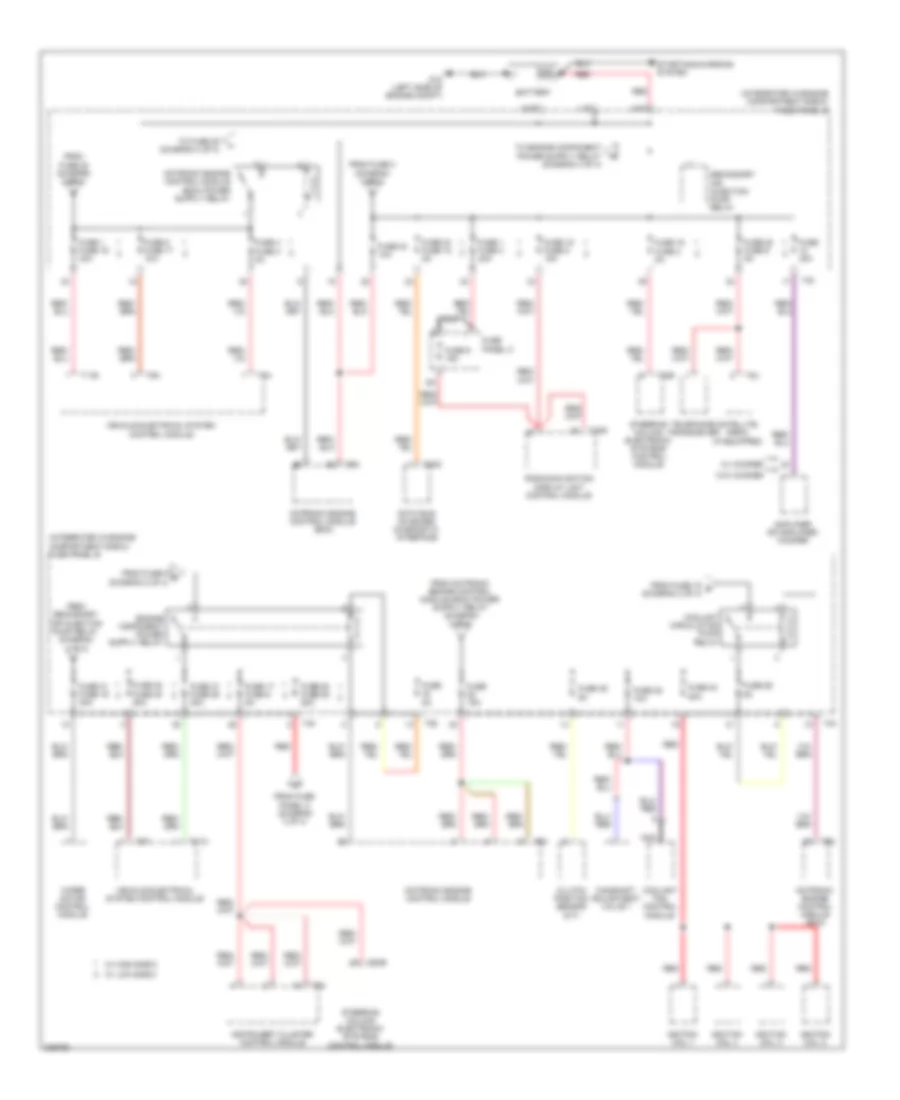
3.2L, Power Distribution Wiring Diagram, Late Production (1 of 4) for Audi A3 2009
List of elements for 3.2L, Power Distribution Wiring Diagram, Late Production (1 of 4) for Audi A3 2009:
- Abs control module
- After-run coolant pump
- Air bag control module
- Battery
- Battery interrupt igniter
- Brake light switch
- Camshaft adjustment valve 1
- Camshaft adjustment valve 1 (exhaust)
- Coolant circulation pump relay
- Coolant fan control (fc) control module
- Direct shift gearbox (dsg) mechatronic
- E-box high
- Evaporative emission (evap) canister purge regulator valve
- Fuse 10a
- Fuse 125a
- Fuse 15a
- Fuse 20a
- Fuse 30a
- Fuse 39 5a
- Fuse 40a
- Fuse 5a
- Fuse 80a
- Fuse panel b
- G51 (at right side of luggage compt)
- G655 (on left headlight)
- Horn relay
- Ignition coil 1
- Ignition coil 2
- Ignition coil 3
- Ignition coil 4
- Ignition coil 5
- Ignition coil 6
- Intake manifold tuning (imt) valve
- L/30
- Leak detection pump (dp)
- Main fuse panel d (right rear of luggage compt)
- Motronic engine control module (ecm)
- Nca
- Red
- Secondary air injection (air) pump relay
- Secondary air injection (air) solenoid valve
- Secondary air injection (air) solenoid valve 2
- Starting/ charging system
- Suppressor
- T20e
- T26
- T2aa
- T2ab
- T2t
- T40
- T52a
- T52c
- Terminal 30 wire junction
- To e-box high a/30 (diagram 2 of 4)
- To e-box high m/30 (diagram 2 of 4)
- To e-box high t40-28 (diagram 2 of 4)
- To fuse panel c-43 (diagram 4 of 4)
- To fuse panel c-7 (diagram 4 of 4)
- Vehicle electrical system control module
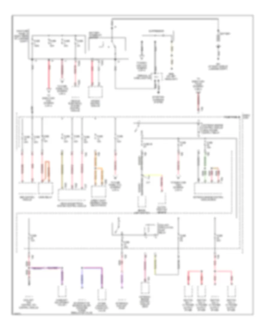
3.2L, Power Distribution Wiring Diagram, Late Production (2 of 4) for Audi A3 2009
List of elements for 3.2L, Power Distribution Wiring Diagram, Late Production (2 of 4) for Audi A3 2009:
- 200a
- A/30
- Amplifier
- Amplifier/ woofer
- Coolant fan control (fc) module
- Cylinder 1 fuel injector
- Cylinder 2 fuel injector
- Cylinder 3 fuel injector
- Cylinder 4 fuel injector
- Cylinder 5 fuel injector
- Cylinder 6 fuel injector
- Data bus on board diagnostic interface
- E-box high
- Electronic damping control module
- From e-box high t40-15 (diagram 1 of 4)
- From main fuse panel d (diagram 1 of 4)
- From suppressor (diagram 1 of 4)
- Fuel pump (fp) 2 relay
- Fuel pump (fp) relay
- Fuse 10a
- Fuse 150a
- Fuse 15a
- Fuse 17 5a
- Fuse 30a
- Fuse 40a
- Fuse 50a
- Fuse 5a
- Fuse 80a
- Fuse panel a
- Fuse panel b
- M/30
- Mass air flow (maf) sensor
- Motronic engine control module
- Motronic engine control module (ecm)
- Nca
- Oxygen sensor (o2s) 1 heater
- Oxygen sensor (o2s) 2 heater
- Oxygen sensor (o2s) heater
- Power steering control module
- Red
- Secondary air injection (air) pump relay
- Starting/ charging system
- Steering column electronic systems control module
- T20b
- T26
- T2a
- T40
- T4d
- To fuse panel c-22 (diagram 4 of 4)
- To fuse panel c-2a diagram (3 of 4)
- To fuse panel c-32 (diagram 4 of 4)
- Transfer fuel pump (fp)
- W/ generator 140a
- W/o generator 140a
- Wiper motor control module
3.2L, Power Distribution Wiring Diagram, Late Production (3 of 4) for Audi A3 2009
List of elements for 3.2L, Power Distribution Wiring Diagram, Late Production (3 of 4) for Audi A3 2009:
- 19a
- 20a
- 40a
- 41a
- 47a
- A/c control module
- Abs control module
- Air bag control module
- Air quality sensor
- All wheel drive control module
- Asr/esp button
- Automatic day/night interior mirror
- Climatronic control module
- Data bus on board diagnostic interface
- Data link connector
- Direct shift gearbox (dsg) mechatronic
- Driver seat heater control module
- Electronic damping control module
- From e-box high t26-5 diagram (2 of 4)
- From e-box high t40-3 (diagram 2 of 4)
- Front passenger seat heater control module
- Front passenger's air bag disabled indicator lamp
- Fuse 10a
- Fuse 15a
- Fuse 19 10a
- Fuse 40a
- Fuse 5a
- Fuse panel c
- G44 (behind left kick panel)
- Garage door opener control head
- Garage door opener control module
- Headlamp range control module
- Heater control module
- High pressure sensor
- Left headlamp power output stage
- Left headlight assembly
- Left washer nozzle heater (if equipped)
- Light switch
- Motronic engine control module
- Nca
- Nca nca
- Oil level thermal sensor
- Parking aid control module
- Positive crank case (pcv) heating element (if equipped)
- Power steering control module
- Rear window wiper motor
- Red
- Red/
- Right headlamp power output stage
- Right headlight assembly
- Right washer nozzle heater (if equipped)
- Seat occupied recognition control module
- Selector lever sensor system control module
- Starting/ charging system
- T100a
- T10e
- T10k
- T16d
- T16f
- T20e
- T26a
- T3w
- T52b
- T8y
- Telephone amplifier
- Vehicle electrical system control module
3.2L, Power Distribution Wiring Diagram, Late Production (4 of 4) for Audi A3 2009
List of elements for 3.2L, Power Distribution Wiring Diagram, Late Production (4 of 4) for Audi A3 2009:
- (diagram 1 of 4)
- 10a
- 12a
- 12v socket
- 13a
- 14a
- 15a
- 16a
- 17a
- 22a
- 23a
- 24a
- 25a
- 26a
- 27a
- 30a
- 32a
- 33a
- 36a
- 37a
- 38a
- 43a
- Abs control module
- Alarm horn (if equipped)
- Cigarette lighter
- Climatronic control module
- Climatronic control module (w/ heated seats)
- Data link connector
- Driver's door control module
- Driver's seat adjustment switch
- Driver's seat lumbar support adjustment switch
- External audio source connection
- Fresh air blower control module
- From e-box high t40-2 (diagram 2 of 4)
- From e-box high-d (fuse panel a) (diagram 2 of 4)
- From fuse panel c e
- From main fuse panel d b
- Front passenger's door control module
- Front passenger's seat adjustment switch
- Front passenger's seat lumbar support adjustment switch
- Fuel pump (fp) 2 relay
- Fuse 10a
- Fuse 15a
- Fuse 20a
- Fuse 30a
- Fuse 40a
- Fuse 5a
- Fuse 7.5a
- Fuse panel c
- G62 (on right "c" pillar)
- G638 (behind right kick panel)
- Headlamp washer relay
- Instrument cluster control module
- Interior lights system
- Left rear door control module
- Nca
- Power sunroof control module
- Radio
- Rain/ light recognizing sensor
- Rear window defogger relay
- Red
- Right rear door control module
- Safety fuse 1
- Selector lever sensor system control module
- Socket
- T10k
- T16d
- T16g
- T20f
- T20g
- T20n
- T20o
- T4w
- T4x
- T52b
- T52c
- T6b
- Telephone transceiver
- Tire pressure monitoring control module
- Vehicle electrical system control module