POWER DISTRIBUTION
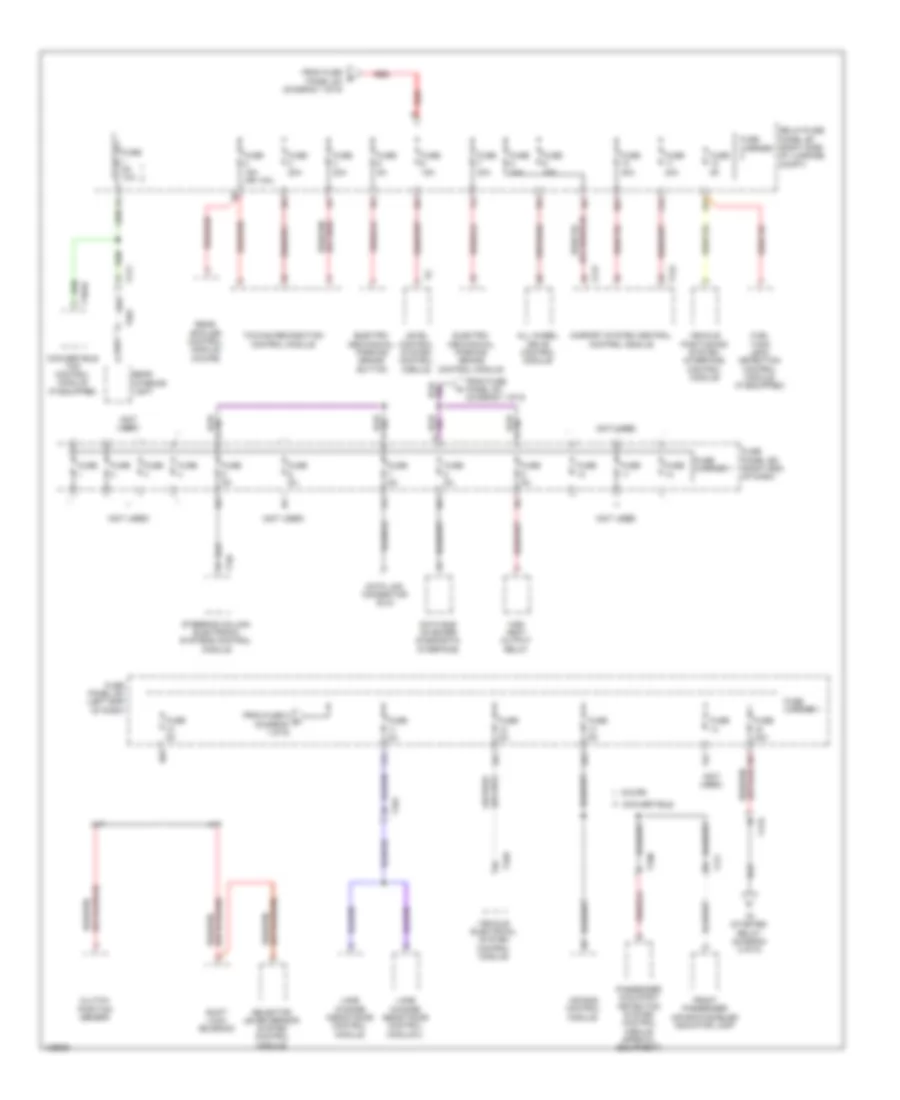
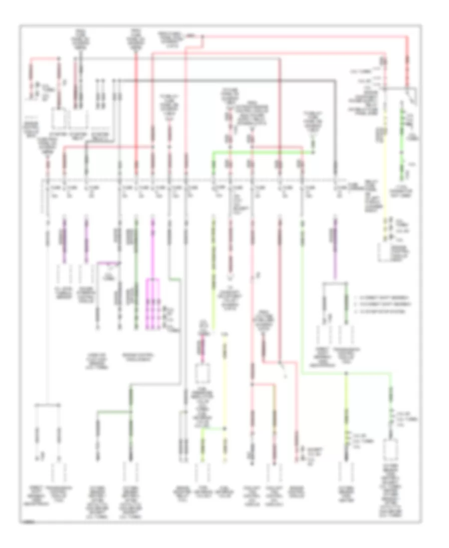
Power Distribution Wiring Diagram (1 of 9) for Audi A5 Quattro Cabriolet 2014

List of elements for Power Distribution Wiring Diagram (1 of 9) for Audi A5 Quattro Cabriolet 2014:
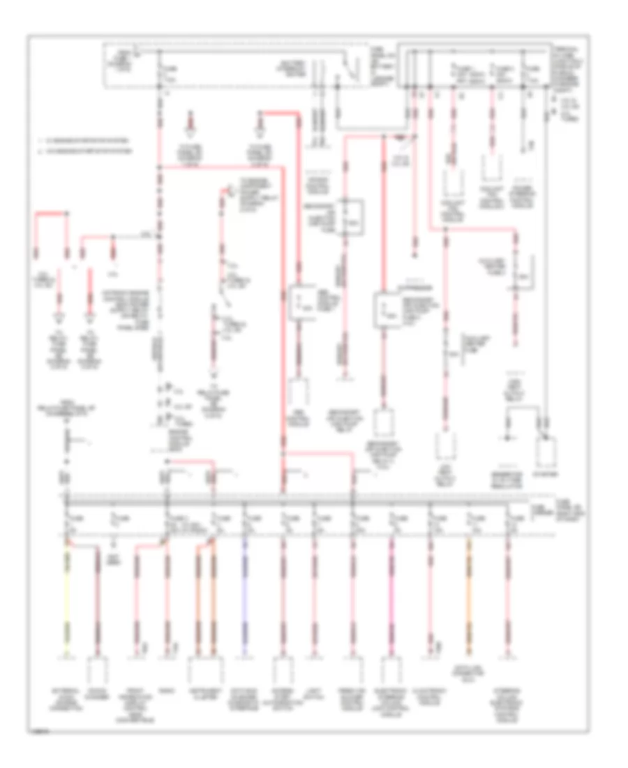
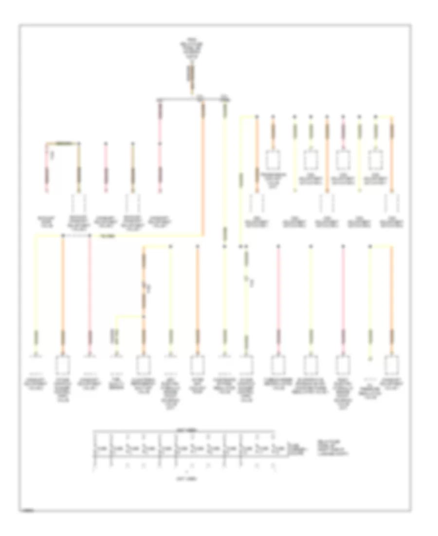
Power Distribution Wiring Diagram (2 of 9) for Audi A5 Quattro Cabriolet 2014
List of elements for Power Distribution Wiring Diagram (2 of 9) for Audi A5 Quattro Cabriolet 2014:
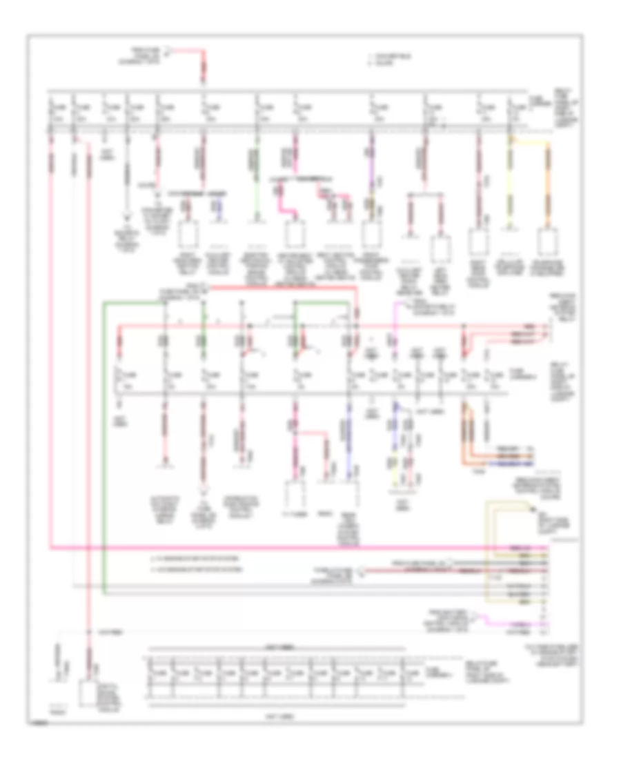
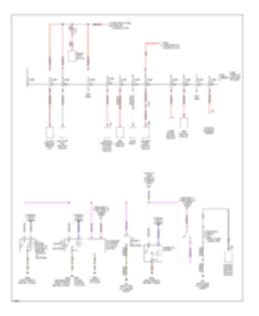
Power Distribution Wiring Diagram (3 of 9) for Audi A5 Quattro Cabriolet 2014
List of elements for Power Distribution Wiring Diagram (3 of 9) for Audi A5 Quattro Cabriolet 2014:
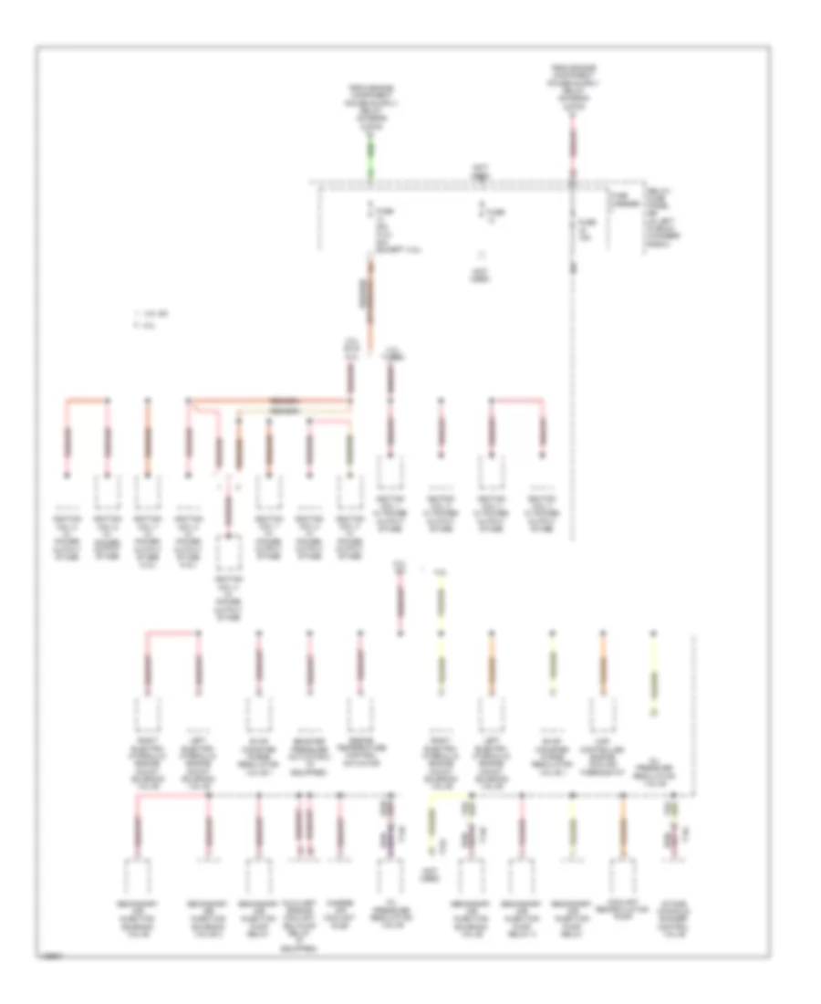
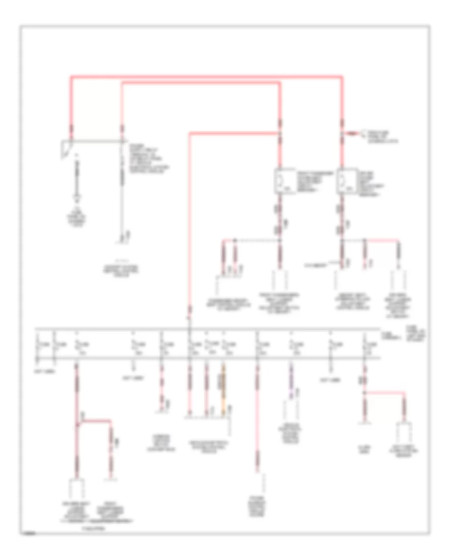
Power Distribution Wiring Diagram (4 of 9) for Audi A5 Quattro Cabriolet 2014
List of elements for Power Distribution Wiring Diagram (4 of 9) for Audi A5 Quattro Cabriolet 2014:
Power Distribution Wiring Diagram (5 of 9) for Audi A5 Quattro Cabriolet 2014
List of elements for Power Distribution Wiring Diagram (5 of 9) for Audi A5 Quattro Cabriolet 2014:
Power Distribution Wiring Diagram (6 of 9) for Audi A5 Quattro Cabriolet 2014
List of elements for Power Distribution Wiring Diagram (6 of 9) for Audi A5 Quattro Cabriolet 2014:
Power Distribution Wiring Diagram (7 of 9) for Audi A5 Quattro Cabriolet 2014
List of elements for Power Distribution Wiring Diagram (7 of 9) for Audi A5 Quattro Cabriolet 2014:
Power Distribution Wiring Diagram (8 of 9) for Audi A5 Quattro Cabriolet 2014
List of elements for Power Distribution Wiring Diagram (8 of 9) for Audi A5 Quattro Cabriolet 2014:
Power Distribution Wiring Diagram (9 of 9) for Audi A5 Quattro Cabriolet 2014
List of elements for Power Distribution Wiring Diagram (9 of 9) for Audi A5 Quattro Cabriolet 2014: