SHIFT INTERLOCK
Electromechanical Parking Brake Wiring Diagram for Audi A7 2012

List of elements for Electromechanical Parking Brake Wiring Diagram for Audi A7 2012:
- (left side of engine compt) abs control module
- (right side of
- Computer data lines system
- Control module
- Cruise control system
- Electro-mechanical
- Electro-mechanical parking brake button
- Fuse 30a
- Fuse 5a
- Fuse carrier
- Fuse panel b (left end of dash)
- Fuse panel f (right rear of luggage compt)
- G51 (right side of luggage compt)
- G687 (right front of center tunnel)
- Hot at all times
- Left parking brake motor (on left rear caliper assembly)
- Luggage compt)
- Parking brake
- Power distribution system
- Right parking brake motor (on right rear caliper assembly)
- T16c
- T32a
- Vehicle electrical system control module
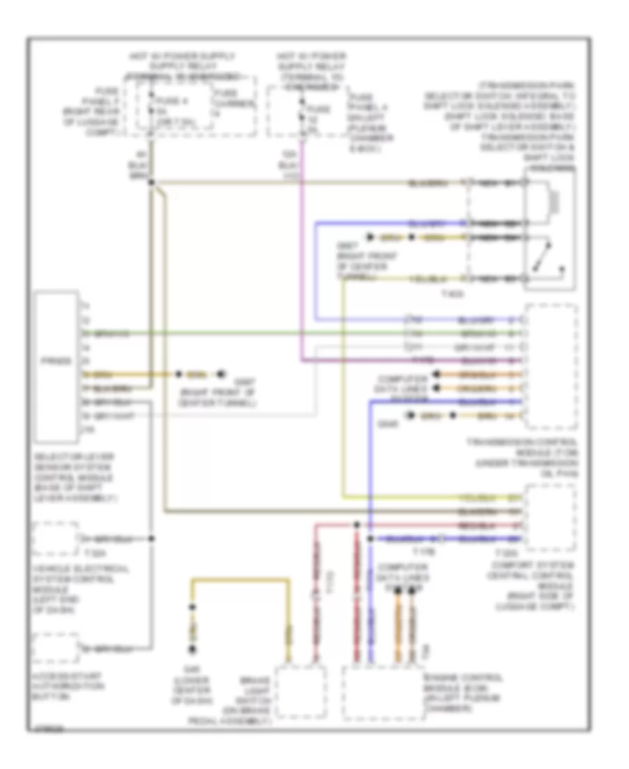
Shift Interlock Wiring Diagram for Audi A7 2012
List of elements for Shift Interlock Wiring Diagram for Audi A7 2012:
- (transmission park selector switch: integral to shift lock solenoid assembly) (shift lock solenoid: base of shift lever assembly) transmission park selector switch & shift lock solenoid
- 12a
- Access/start authorization button
- Brake light switch (on brake pedal assembly)
- Comfort system central control module (right side of luggage compt)
- Computer data lines system
- Engine control module (ecm) (in left plenum chamber)
- Fuse 4 5a (or 7.5a)
- Fuse 5a
- Fuse carrier
- Fuse panel a (in left plenum chamber e-box)
- Fuse panel f (right rear of luggage compt)
- G45 (lower center of dash)
- G645
- G687 (right front of center tunnel)
- Nca
- Prnds
- Selector lever sensor system control module (base of shift lever assembly)
- T17a
- T17b
- T17o
- T32a
- T32g
- T4ca
- T94
- Transmission control module (tcm) (under transmission oil pan)
- Vehicle electrical system control module (left end of dash)
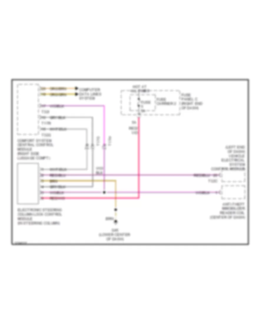
Steering Column Wiring Diagram for Audi A7 2012
List of elements for Steering Column Wiring Diagram for Audi A7 2012:
- (left end of dash) vehicle electrical system control module
- Anti-theft immobilizer reader coil (center of dash)
- Comfort system central control module (right side luggage compt)
- Computer data lines system
- Electronic steering column lock control module (in steering column)
- Fuse 5a
- Fuse carrier 2
- Fuse panel c (right end of dash)
- G45 (lower center of dash)
- Hot at all times
- T17h
- T17o
- T17r
- T32c
- T32g
- T32i