AIR CONDITIONING
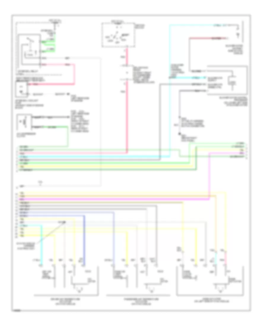
Automatic A/C Wiring Diagram (1 of 3) for Cadillac CTS 2004

List of elements for Automatic A/C Wiring Diagram (1 of 3) for Cadillac CTS 2004:
- 3.2l
- 5 volt reference
- After boil pump relay ctrl
- Air inlet motor
- Amb air temp sensor sig
- Ambient light sensor signal
- Battery
- Blower fuse 40a
- Blower mtr speed ctrl
- Blower relay
- Blower relay ctrl
- Ccp fuse 10a
- Cmp clu relay
- Comp clutch fuse 10a
- Computer data lines system
- Coolant level switch signal
- Door a
- Door b
- Dr air temp door ctrl b
- Driver air temp door ctrl a
- Driver air temp posit signal
- E10
- E11
- E12
- E13
- E14
- E15
- E16
- Evap low temp sens signal
- Evaporator temperature sensor (on right side of evaporator case)
- F10
- F11
- F12
- F13
- F14
- F15
- F16
- G201 (behind right kick panel)
- Ground
- Hot at all times
- Hot in run
- Hvac control module (behind center of dash, below radio)
- Ign 3 fuse 10a
- Ignition 3 voltage
- Inside air temp sensor sig
- Inside air temperature sensor
- Joint connector
- Left rear fuse block (below left rear seat)
- Left sunload sensor signal
- Low reference
- Mode door ctrl a
- Mode door ctrl b
- Mode door position signal
- Nca
- Pass air temp door ctrl a
- Pass air temp door ctrl b
- Pass air temp posit signal
- Pnk
- R51
- R52
- R53
- R54
- R55
- R56
- R57
- R58
- Recirc door ctrl a
- Recirc door ctrl b
- Recirculation actuator (left side of the blower motor)
- Right sunload sensor signal
- S117
- Serial data
- Solid state
- Splice pack sp302
- Sunload sensor (top center of i/p, on defrost grill)
- Tan
- Underhood fuse block (right front of engine compartment)
- Volt
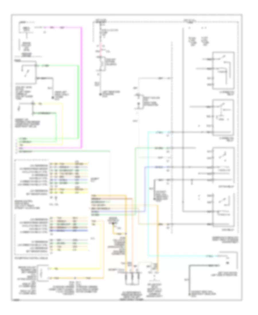
Automatic A/C Wiring Diagram (2 of 3) for Cadillac CTS 2004
List of elements for Automatic A/C Wiring Diagram (2 of 3) for Cadillac CTS 2004:
- (3.2l)
- (3.6l)
- (5.7l)
- (in blower motor harness, 115 cm from c323) s323
- (in hvac module harness, 6 cm from c321)
- 3.2l
- A/c
- A/c compressor clutch
- Acc
- After boil coolant pump (on right side of engine block)
- After boil fuse 10a
- After boil relay (3.2l)
- Blower motor (on right side of hvac module)
- Blower motor control processor (on lower left side of blower motor)
- Blower mtr speed ctrl
- Cold
- Def
- Driver air temperature actuator (on hvac module)
- Dry air temp signal
- G100 (left rear side of engine)
- G100 (left rear side of engine) g132 (front of right cylinder head) g142 (rear of right cylinder head)
- G201 (behind right kick panel)
- Hot
- Hot at all times
- Ignition switch
- Lock
- Logic
- Mix motor
- Mode actuator
- Mode actuator (on left side of hvac module)
- Mode valve signal
- Nca
- Off
- Pass air temp signal
- Passenger air temperature actuator (on hvac module)
- Pnk
- R11
- R12
- R13
- R15
- Right rear fuse block (below right rear seat)
- Run
- S118
- S202 (in the i/p harness, 48 cm from hazard switch connector)
- Splice pack sp200 (in right front of passenger compt, under dash, above steering column)
- Start
- Tan
Automatic A/C Wiring Diagram (3 of 3) for Cadillac CTS 2004
List of elements for Automatic A/C Wiring Diagram (3 of 3) for Cadillac CTS 2004:
- (3.2l)
- (except 3.2l) a
- (left rear side of engine) g100
- (near left front strut tower) g101
- (on right body rail, near right headlamp) g104
- (or 452)
- (or 470)
- 26 cm from starter motor connector)
- 3.2l
- 3.2l 3.6l
- 3.6l
- 5.7l
- 5v reference
- A/c clutch relay ctrl
- A/c refrig press sensor
- A/c refrigerant pressure sensor (near the left front strut tower)
- Ambient air temperature sensor (under front bumper, near front grille)
- Coolant bypass solenoid
- Coolant level switch (in left front corner of coolant surge tank)
- Ect sensor signal
- Engine control module (ecm) (3.6l (vin 7): front of right valve cover)
- Engine controls system
- Engine coolant low level
- Engine coolant temperature (ect) sensor (3.2l: rear of intake manifold) (3.6l: side of left cylinder head) (5.7l: front of left cylinder head)
- Except 5.7l
- Feed
- Hi speed fan relay
- Hi speed fan relay ctrl
- High fan fuse 30a
- Hot at all times
- Hot in on or start
- Htr vlv/cltch fuse 10a
- Left cooling fan (left side of radiator)
- Lo speed fan relay
- Logic
- Low fan fuse 30a
- Low reference
- Low speed fan relay ctrl
- Main relay
- Main relay ctrl
- Message center
- Pnk
- Powertrain control module
- R14
- R15
- R16
- R17
- R18
- R19
- R20
- R21
- R22
- R39
- R40
- R41
- R42
- R47
- R48
- R49
- R50
- Radio
- Right cooling fan (right side of radiator)
- Rtn
- S/p fan relay
- S111 s148 (3.6l) (3.2l) (in engine harness, (in engine harness under throttle body, 11.5 cm towards the right)
- S156 (3.6l (vin 7)) (in engine harness, approximately 24 cm from ebcm connector)
- Serial data
- Sig
- Splice pack sp102 (except 5.7l) (right front corner of engine compt)
- Tan
- Underhood fuse block (right front of engine compartment)
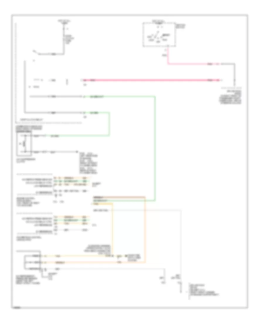
Compressor Wiring Diagram for Cadillac CTS 2004
List of elements for Compressor Wiring Diagram for Cadillac CTS 2004:
- (3.2l)
- (3.6l)
- (5.7l)
- (in engine harness, approximately 24 cm from ebcm connector) (3.6l (vin 7)) s156
- (or tan)
- 3.2l
- 3.6l
- 470 (or 452)
- 5.7l
- 5v reference
- A/c clutch relay ctrl
- A/c compressor clutch
- A/c refrig press sens sig
- A/c refrigerant pressure sensor (near the left front strut tower)
- Acc
- Comp clutch fuse 10a
- Comp clutch relay
- Computer data lines system
- Engine control module (ecm) (3.6l: front of right valve cover)
- Except 3.2l
- Except 5.7l
- Feed
- G100 (left rear side of engine) g132 (front of right cylinder head) g142 (rear of right cylinder head)
- Hot at all times
- Ignition switch
- Lock
- Low reference
- Nca
- Off
- Pnk
- Powertrain control module (pcm)
- R55
- R56
- R57
- R58
- Return
- Run
- Sig
- Splice pack sp102 (except 5.7l) (right front corner of engine compartment)
- Splice pack sp200 (in right front of passenger compt, under dash, above steering column)
- Start
- Tan
- Underhood fuse block (right front of engine compartment)