POWER DISTRIBUTION
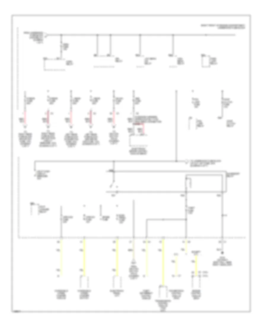
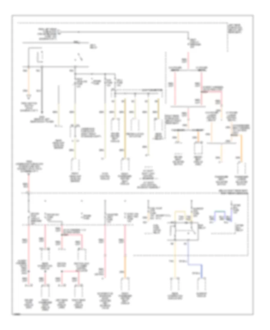
Power Distribution Wiring Diagram (1 of 7) for Cadillac CTS 2004

List of elements for Power Distribution Wiring Diagram (1 of 7) for Cadillac CTS 2004:
- (3.2l)
- (3.6l)
- (except 3.2l)
- (in engine harness, 15 cm from coil 1) s145
- (in fuel injector harness, 15 cm from c121) s151
- (in fuel injector harness, near c112) s108
- (in ignition coil/module harness, on left valve cover, 5 cm from c131) s163
- (in the engine harness, 45 cm from the underhood fuse block) s132
- (not used)
- (right front of engine compartment) underhood fuse block
- 3.2l
- 3.6l
- 5.7l
- A/t
- Battery
- Blower fuse 40a
- Blower relay
- C1 g
- C2 a12
- Ccp fuse 10a
- Dash integration module (dim)
- Data link connector (dlc)
- Dim/ aldl fuse 10a
- Ecm fuse 15a
- Ecm/tcm fuse 10a
- Engine control module (ecm)
- Evaporative emission (evap) canister purge solenoid valve
- Evaporative emissions (evap) canister purge solenoid valve
- Except 5.7l
- Flasher fuse 15a
- Fuel injector
- Fusible link
- Generator
- Heated oxygen sensor (ho2s) bank 1 sensor 2
- Heated oxygen sensor (ho2s) bank 2 sensor 2
- Hi fan fuse 30a
- Hi speed fan relay
- Hvac control module
- Ignition coil 1
- Ignition coil 3
- Ignition coil 5
- Ignition coil/ module 1
- Ignition coil/ module 3
- Ignition coil/ module 5
- Ignition coil/ module 7
- Ignition manifold runner control (imrc) solenoid
- Instrument panel cluster (ipc)
- Intake manifold tuning valve (imtv) solenoid
- Left rear fuse block (below left rear seat)
- Low fan fuse 30a
- Low speed fan relay
- Main relay
- Mass air flow (maf) sensor
- Odd inj/ coil fuse 15a
- Post 2 fuse 15a
- Powertrain control module (pcm)
- Pusher fan relay
- R14
- R19
- R20
- R39
- R40
- R47
- R48
- R49
- R50
- R51
- R52
- S/p fan relay
- Spare fuse
- Starter
- Theft deterrent control module
- To underhood fuse block (horn relay) (diagram 2 of 7)
- To underhood fuse block (pre 2/cam fuse, 15a) (diagram 3 of 7)
- Tos fuse 10a
- Trailer provisions
- Transmission control module (tcm)
- Turn signal/ hazard flasher module
- Vehicle speed sensor (vss) (manual transmission)
- Volt check fuse 10a
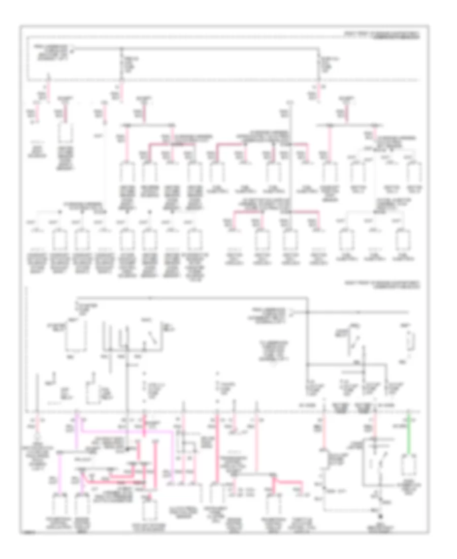
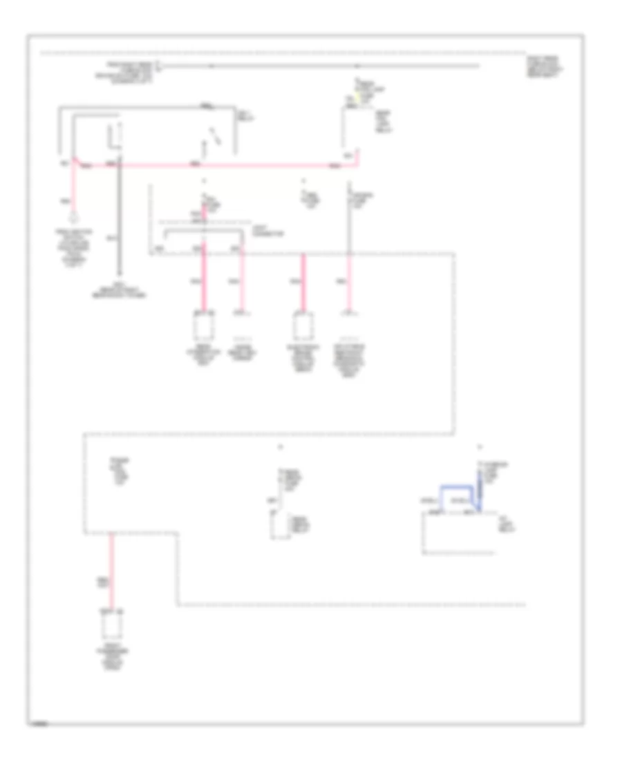
Power Distribution Wiring Diagram (2 of 7) for Cadillac CTS 2004
List of elements for Power Distribution Wiring Diagram (2 of 7) for Cadillac CTS 2004:
- (3.2l)
- (3.6l)
- (in engine harness, approximately 8 cm from ebcm connector) s130
- (right front of engine compartment) underhood fuse block
- 5.7l
- Abs fuse 50a
- Accessory relay
- Comp clutch fuse 10a
- Comp clutch relay
- Drl relay
- Elec prndl fuse 10a
- Electronic brake control module (ebcm)
- Electronic prndl (a/t)
- Engine control module (ecm)
- Except 5.7l
- Fog lamp fuse 15a
- Fog lamp relay
- From ignition switch (pin 2) (diagram 4 of 7)
- From underhood fuse block a (main relay) (diagram 1 of 7)
- G104 (on right body rail, near right headlamp)
- Hdlp wash circuit breaker 30a
- Hdlp washer relay
- High beam relay
- Horn fuse 15a
- Horn relay
- Ign sw fuse 10a
- L rear fuse 60a
- Low beam/ hid relay
- Park lamp relay
- Powertrain control module (pcm)
- R rear fuse 60a
- R10
- R11
- R24
- R28
- R32
- R35
- R36
- R37
- R38
- R56
- R68
- Spare fuse
- Theft deterrent control module
- Theft fuse 7.5a
- To ignition switch (pin 6) (diagram 4 of 7)
- To left rear fuse block (driver dr mod fuse, 10a) (diagram 5 of 7)
- To left rear fuse block (pusher fan fuse, 30a) (diagram 5 of 7)
- To right rear fuse block (dr mod pwr circuit breaker, 30a) (diagram 6 of 7)
- To right rear fuse block (rim/ign sw fuse, 10a) (diagram 4 of 7)
- To underhood fuse block (i/p out let fuse, 20a) (diagram 3 of 7)
- Transmission control module (tcm) (a/t)
- Windshield wiper/ washer module
- Windshield wiper/ washer switch
- Wpr mod fuse 30a
- Wpr sw fuse 10a
Power Distribution Wiring Diagram (3 of 7) for Cadillac CTS 2004
List of elements for Power Distribution Wiring Diagram (3 of 7) for Cadillac CTS 2004:
- (3.2l)
- (3.6l)
- (a/t)
- (accessory relay) (diagram 2 of 7)
- (in body harness, 22 cm from a/c pressure switch connector)
- (in engine harness, 15 cm from coil 5) s142
- (in engine harness, 24.5 cm from ect sensor) s146
- (in engine harness, approximately 20 cm from underhood fuse block) s162
- (in fuel injector harness, 15 cm from c121) s152
- (in ignition coil/module harness, on right valve cover, 5 cm from c132) s164
- (on right body rail, near right headlamp) g104
- (right front of engine compartment) underhood fuse block
- 3.2l
- 3.6l
- 5.7l
- A/t
- A8 c2
- Auxiliary power outlet
- B+ mode
- Battery saver mode
- Camshaft actuator solenoid exhaust bank 1
- Camshaft actuator solenoid exhaust bank 2
- Camshaft actuator solenoid intake bank 1
- Camshaft actuator solenoid intake bank 2
- Camshaft position (cmp) sensor
- Cigar lighter
- Cigar relay
- Clutch pedal position (cpp) sensor
- Cmp clu relay
- Coolant bypass valve solenoid
- Dash integration module (dim)
- Engine control module (ecm)
- Evaporative emission (evap) canister purge solenoid valve
- Even inj/ coil fuse 15a
- Except 3.6l
- Except 5.7l
- Fog lamp relay
- From ignition switch (via splice pack sp200) (pin 8) (diagram 4 of 7)
- From underhood fuse block b (ecm fuse, 15a) (diagram 1 of 7)
- From underhood fuse block h
- Fuel injector 2
- Fuel injector 4
- Fuel injector 6
- Fuel injector 8
- G201 (behind right kick panel)
- Heated oxygen sensor (ho2s) bank 1 sensor 1
- Heated oxygen sensor (ho2s) bank 2 sensor 1
- Htr vlv/ cltch fuse 10a
- I/p outlet fuse 20a
- Ign 1 relay
- Ignition coil 2
- Ignition coil 4
- Ignition coil 6
- Ignition coil/ module 2
- Ignition coil/ module 4
- Ignition coil/ module 6
- Ignition coil/ module 8
- Instrument panel cluster (ipc)
- Intake manifold runner control (imrc) solenoid
- M/t
- Outlet fuse 30a
- Pnk
- Pnk a
- Pnk/ (in engine harness, 15.5 cm from c101) s170
- Powertrain control module (pcm)
- Pre o2/ cam fuse 15a
- R43
- R44
- R45
- R46
- R55
- R59
- R60
- R61
- R62
- R63
- R64
- Reverse lockout solenoid
- S131
- S202
- S308
- Skip shift solenoid
- Splice pack sp200
- Starter fuse 30a
- Starter relay
- Tcm/ipc fuse 15a
- Throttle actuator control (tac) module
- To underhood fuse block (wash noz fuse, 10a) (diagram 4 of 7)
- Transmission control module (tcm)
Power Distribution Wiring Diagram (4 of 7) for Cadillac CTS 2004
List of elements for Power Distribution Wiring Diagram (4 of 7) for Cadillac CTS 2004:
- (3.2l)
- (3.6l)
- (in steering column harness, 12.7 cm from c202) s207
- 3.2l
- 3.2l & 3.6l
- 3.6l
- 5.7l
- A11
- Acc
- Accessory
- Cruise control switch
- Cruise control switch fuse 2a
- Dash integration module (dim)
- Engine control module (ecm)
- Except 5.7l
- From underhood fuse block (ign sw fuse, 10a) (diagram 2 of 7)
- From underhood fuse block (r rear fuse, 60a) (connector c3, pin 1) (diagram 2 of 7)
- From underhood fuse block (tcc/et fuse, 10a) (diagram 3 of 7)
- Ign mod/maf fuse 15a
- Ignition 1
- Ignition coil bank 1 (3.2l)
- Ignition coil bank 2
- Ignition lock cylinder control actuator
- Ignition switch
- Inflatable restraint steering wheel module coil
- Left headlamp
- Left heated washer nozzle
- Mass air flow (maf) sensor
- Off/lock
- Pnk
- Powertrain control module (pcm)
- Rear integration module (rim)
- Right headlamp
- Right heated washer nozzle
- Right rear fuse block (below right rear seat)
- Right steering wheel controls
- Rim/ ign sw fuse 10a
- Run
- S200 (in the i/p harness, 11.5 cm from sp200)
- Spare fuse
- Splice pack sp200
- Start
- Steering column fuse block (taped to steering column harness)
- Strg ctls fuse 10a
- To left rear fuse block (ign 3 relay) (diagram 6 of 7)
- To right rear fuse block (ign 1 relay) (diagram 7 of 7)
- To underhood fuse block (accessory relay) (connector c4, pin 37) (diagram 2 of 7)
- To underhood fuse block (cmp clu relay) (diagram 3 of 7)
- Turn signal switch
- Turn signal/ multifunction switch
- Underhood fuse block (right front of engine compartment)
- W/ automatic headlamps control leveling system
- Wash noz fuse 10a
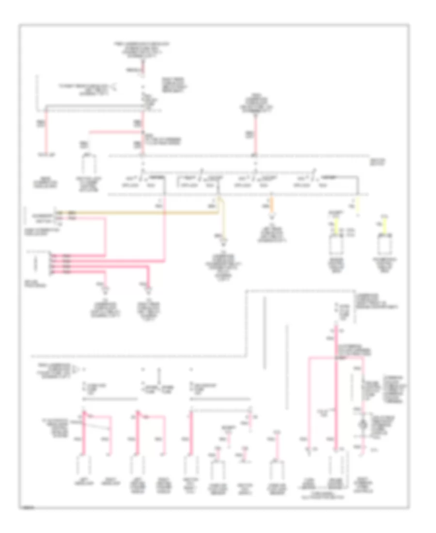
Power Distribution Wiring Diagram (5 of 7) for Cadillac CTS 2004
List of elements for Power Distribution Wiring Diagram (5 of 7) for Cadillac CTS 2004:
- (below left rear seat) left rear fuse block
- (in driver seat harness, 8 cm from msm connector) s351
- (in headliner harness, 22.5 cm from radio antenna module) s313
- A12
- Amp fuse 30a
- Audio amplifier
- Audio fuse 10a
- Bas fuse 15a
- Bas relay
- Digital radio receiver
- Driver adjuster seat switch
- Driver door module (ddm)
- Driver dr mod fuse 10a
- Driver heated seat module
- Driver lumbar adjuster switch
- F11
- From underhood fuse block (l rear fuse, 60a) (connector c2, pin 1) (diagram 2 of 7)
- From underhood fuse block (l rear fuse, 60a) (connector c2, pin 2) (diagram 2 of 7)
- Garage door opener
- Joint connector
- L frt htd seat mod fuse 10a
- Left rear door module (lrdm)
- Left rear fuse block (ign 3 relay) (diagram 6 of 7)
- Mem/adapt seat fuse 10a
- Memory seat module (msm)
- Pusher fan fuse 30a
- Pusher fan relay (trailer provisions)
- R31
- R32
- R36
- R37
- Radio
- Radio antenna module
- Rear dr mod fuse 15a
- Rev lamp relay
- Reverse lamp fuse 10a
- Right rear door module (rrdm)
- S12
- S13
- S14
- S15
- S17
- S18
- S19
- S20
- S21
- S22
- S23
- Spare fuse
- Trk dr rel sol relay
- Trunk dr release fuse 10a
- Vehicle communication interface module (vcim)
- W/ 7 speaker system
- W/o 7 speaker system
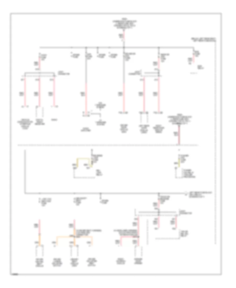
Power Distribution Wiring Diagram (6 of 7) for Cadillac CTS 2004
List of elements for Power Distribution Wiring Diagram (6 of 7) for Cadillac CTS 2004:
- (below right rear seat) right rear fuse block
- (except 5.7l) (5.7l)
- (in body harness, 108 cm from c700) s304
- (in body harness, 108 cm from c800) s303
- (in i/p harness, 11.5 cm from sp200) s200
- (in passenger seat harness, 12.7 cm from c307) s352
- A/t shift lock control solenoid assembly
- A/t shift shift lock control solenoid
- A11
- After boil fuse 10a
- After boil relay
- Canister vent fuse 10a
- Ccp fuse 10a
- Dr mod pwr circuit breaker 30a
- Driver door module (ddm)
- Driver heated seat module
- Driver seat adjuster switch
- Evaporative emissions (evap) canister vent solenoid valve
- From ignition switch (pin 5) (diagram 4 of 7)
- From left rear fuse block (trk dr release fuse, 10a) (diagram 5 of 7)
- From underhood fuse block (r rear fuse, 60a) (connector c3, pin 2) (diagram 2 of 7)
- Front headlamp leveling sensor
- Front passenger door module (fpdm)
- Front passenger heated seat module
- Fuel pump motor relay
- Fuel pump mtr fuse 15a 20a
- G402 (rear of left rear shock tower)
- Hdlp leveling fuse 10a
- Hvac control module
- Ign 3 fuse 10a
- Ign 3 relay
- Ignition lock cylinder control actuator
- Ignition switch
- Joint connector
- Left rear door module (lrdm)
- Left rear fuse block (below left rear seat)
- Memory seat module (msm)
- Passenger lumbar adjuster switch
- Passenger seat adjuster switch
- R frt htd seat mod fuse 10a
- R11
- R12
- R21
- R22
- R23
- R25
- R37
- Rap relay
- Rear defog relay
- Rear headlamp leveling sensor
- Rear integration module
- Rear integration module (rim)
- Recirculation actuator
- Right rear door module (rrdm)
- Right rear fuse block (below right rear seat)
- Rim/ign sw fuse 10a
- Seat circuit breaker 30a
- Spare fuse
- Sunroof module
- Tan
- Underhood fuse block (right front of engine compt)
- W/ memory
- W/ power lumbar control seats
- W/ power seats
- W/o memory
- W/o power lumbar control seats
- W/o power seats
Power Distribution Wiring Diagram (7 of 7) for Cadillac CTS 2004
List of elements for Power Distribution Wiring Diagram (7 of 7) for Cadillac CTS 2004:
- A12
- Abs fuse 10a
- Air bag fuse 10a
- Electronic brake control module (ebcm)
- From ignition switch (via splice pack sp200, pin 9) (diagram 4 of 7)
- From right rear fuse block (rim/ign sw fuse, 10a) (diagram 4 of 7)
- Front passenger door module (fpdm)
- G401 (rear of right rear shock tower)
- Ign 1 relay
- Inflatable restraint sensing & diagnostic module (sdm)
- Inside rear view mirror
- Int lamp relay
- Interior lamp fuse 10a
- Joint connector
- Pnk
- Psgr dr mod fuse 10a
- R16
- R17
- R21
- R22
- R23
- R25
- R31
- R32
- Rear defog fuse 40a
- Rear defog relay
- Rear fog lamp fuse 10a
- Rear fog lamp relay
- Rear integration module (rim)
- Right rear fuse block (below right rear seat)
- Rim fuse 10a
- S20
- S21
- S22
- S23