AIR CONDITIONING
Automatic A/C Wiring Diagram (1 of 2) for Cadillac XLR 2005

List of elements for Automatic A/C Wiring Diagram (1 of 2) for Cadillac XLR 2005:
- (in instrument panel harness, approximately 5
- A/c comp fuse 15 10a
- A/c comp relay 35
- A/c compressor clutch
- A/c off switch
- B12
- Bat
- Blower ctrl
- Blower speed switch
- Body control module (bcm) (behind right side of dash)
- C1 c10
- C4 d8 pnk
- Cm (1.9 in) from blower motor control module connector breakout)
- Coolant level switch (left side of engine compt)
- Coolfan fuse 32 40a
- Defog rly ctrl
- Defogger system
- Defrost frost
- Defrost switch
- Dr ctrl a
- Dr ctrl b
- E1 c2
- F13
- F14
- F7 c3
- G101
- G102
- G202
- Gnd
- H13
- H14
- Hot at all times
- Hot w/ run/ crank relay energized
- Hvac control module (at center of dash)
- Hvac fuse 28 40a
- Hvac/ pwr send fuse 9 10a
- Ign
- Ign 1 relay 44
- Ign 1 voltage
- Ind ctrl
- Info not available
- Interior lights system
- Isrvm/ hvac fuse 14 10a
- Lamp ctrl
- Left air temperature switch
- Light sens sig
- Logic
- Low ref
- Mirrors system
- Mode ctrl
- Mode switch
- Mtr spd ctrl
- Off ctrl
- Pnk
- Recirc ctrl
- Recirculation switch
- Right air temperature switch
- S231
- Seats system
- Sens sig
- Serial data
- Speed ctrl
- Splice pack sp101 (in forward lamp harness, in engine compartment, on upper left frame rail, grounded to g101)
- Splice pack sp102 (in forward lamp harness, in engine compartment, on upper right frame rail, grounded to g102)
- Splice pack sp202 (in instrument panel harness, in passengers compartment, at base of right a pillar behind trim panel, grounded to g202)
- Sply voltage
- Sply voltage 4
- Sunload sig
- Tan
- Temp ctrl
- Temp ctrl sig
- Transmissions system
- Underhood fuse block (right rear of engine compt)
- Valet sw sig
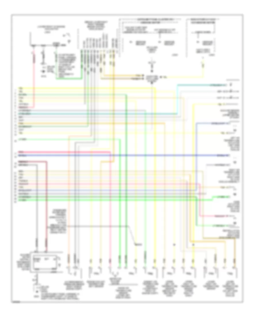
Automatic A/C Wiring Diagram (2 of 2) for Cadillac XLR 2005
List of elements for Automatic A/C Wiring Diagram (2 of 2) for Cadillac XLR 2005:
- (behind lower right front fender) engine control module (ecm)
- (in instrument panel harness, in passengers compartment, at base of right a pillar behind trim panel, grounded to g202)
- (lower front of engine) cooling fan
- (passenger power seat harness, approximately
- 4.0 cm (1.5
- 5v ref
- A/c refrigerant pressure sensor (right side of engine compt)
- Ambient air temperature sensor (lower right front of engine compt)
- Aspirator blower motor
- Bat
- Blower motor control processor (right side of blower motor)
- Check gages
- Computer data lines system
- Coolant over temp engine hot/stop engine low coolant
- Engine coolant temperature (ect) sensor
- G102
- G202
- Gnd
- Head up display (hud)
- Hot engine-a/c off service a/c
- Hud class 2 serial data
- Hud message center
- In) from breakout for passenger seat relay center connector c1)
- Inside air temperature sensor (lower left side of dash)
- Instrument panel cluster (ipc)
- Ipc class 2 serial data
- Left air temperature actuator (left side of hvac module)
- Logic
- Low ref
- Low ref c2 tan
- Lower left air temperature sensor (on left side of hvac module)
- Lower right air temperature sensor
- Message center
- Message request
- Mode actuator (right side of hvac module)
- Pnk
- Recirculation actuator (right side of blower motor)
- Right air temperature actuator (right side of hvac module assembly)
- Rly ctrl
- S242
- Sens sig
- Serial data +
- Serial data - c1 tan
- Spd ctrl
- Speed ctrl
- Splice pack sp102
- Splice pack sp202 (in instrument panel harness, in passengers compt, at base of right a pillar behind trim panel)
- Sunload sensor assembly (upper center of dash)
- Tan
- Upper left air temperature sensor (behind left center of dash)
- Upper right air temperature sensor (upper right of dash)
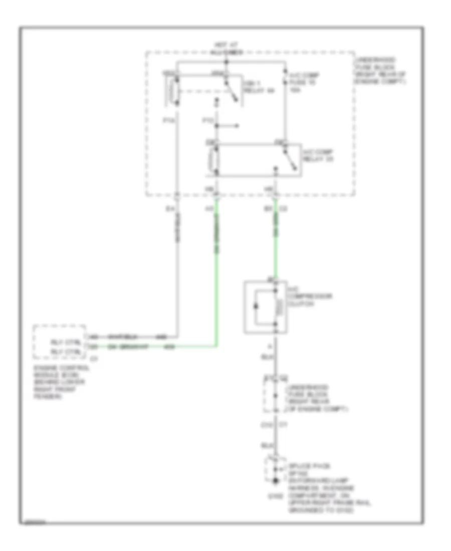
Compressor Wiring Diagram for Cadillac XLR 2005
List of elements for Compressor Wiring Diagram for Cadillac XLR 2005:
- A/c comp fuse 15 10a
- A/c comp relay 35
- A/c compressor clutch
- C1 c10
- E1 c2
- Engine control module (ecm) (behind lower right front fender)
- F13
- F14
- G102
- H13
- H14
- Hot at all times
- Ign 1 relay 44
- Rly ctrl
- Splice pack sp102 (in forward lamp harness, in engine compartment, on upper right frame rail, grounded to g102)
- Underhood fuse block (right rear of engine compt)