ANTI-THEFT
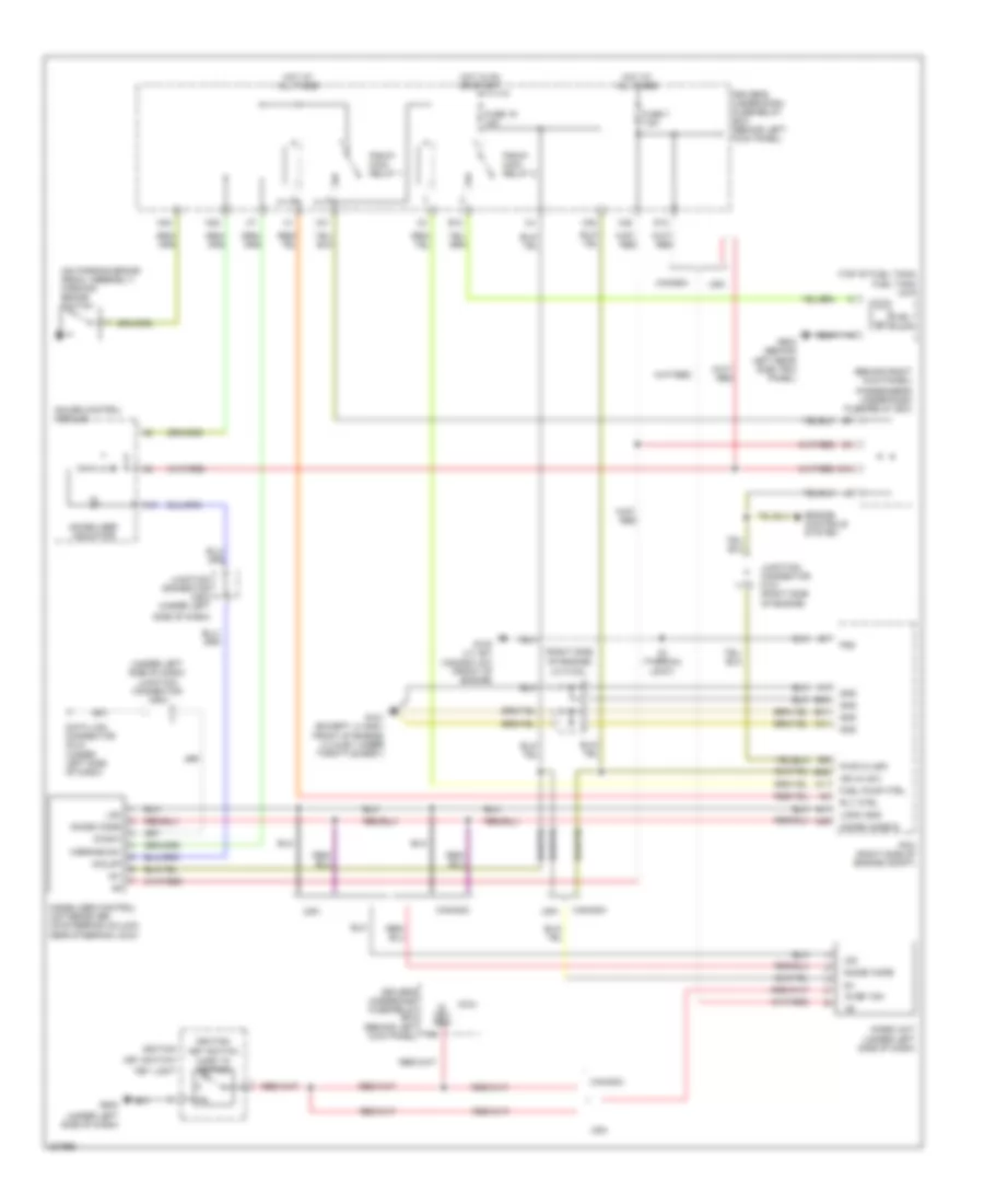
Forced Entry Wiring Diagram for Honda Odyssey Touring 2010

List of elements for Forced Entry Wiring Diagram for Honda Odyssey Touring 2010:
- (behind right rear side trim panel) micu-rear junction box
- (on right "c" pillar) right sliding door switch
- A14
- A25
- B-can drswdr
- Body controller area network transceiver
- Driver's door switch (on left "b" pillar)
- Driver's under-dash fuse/relay box (behind left kick panel)
- Drswas
- Drswra
- Drswrd
- E14
- E15
- Front passenger's door switch (on right "b" pillar)
- Fuse 33 2a
- G60
- G701 (behind right rear side trim panel)
- Gauge control module
- H12
- H13
- Hot at all times
- Left sliding door switch (on left "c" pillar)
- Micro- phone jack
- Microphone
- Micu
- Micu-rear junction box control unit
- N28
- Nca
- Security control unit
- Tailgate latch switch
Immobilizer Wiring Diagram for Honda Odyssey Touring 2010
List of elements for Immobilizer Wiring Diagram for Honda Odyssey Touring 2010:
- (behind right kick panel)
- (on parking brake pedal assembly) parking brake switch
- (right side of engine)
- (top of fuel tank) fuel tank unit
- (under left side of dash)
- (under left side of dash) junction connector c503
- 1=key in ignition
- A11
- A16
- A41
- A46
- B40
- B41
- B42
- C41
- Canada
- D12
- Data link connector (dlc) (under left side of dash)
- Diag-h
- Driver's under-dash fuse/relay box (behind left kick panel)
- Driver's underdash fuse/relay box (behind left kick panel)
- E13
- E14
- Engine controls system
- Fuel pump
- Fuel pump ctrl
- Fuse 19 15a
- Fuse 7 7.5a
- G101 (except lx & ex: front of engine) (lx & ex: under throttle body)
- G102 (lx, ex; canada: dx) (front of engine)
- G502
- G603 (behind left rear side trim panel)
- Gauge control module
- Gnd
- H/brake sw
- Hot at all times
- Hot in on or start
- Ig key sw
- Ig1
- Ign in (ig1)
- Ignition
- Ignition key switch
- Immobi code
- Immobi code in
- Immobilizer control unit-receiver (on steering column, near steering lock)
- Immobilizer indicator
- Imoes unit (under left side of dash)
- Imolmp
- J/c c102
- Junction connector c101 (right side of engine)
- Junction connector c503 (under left
- Key light
- Key switch/
- Lg3
- Logic gnd
- Micu
- N30
- N34
- Passenger's under-dash fuse/relay box
- Pcm (right side of engine compt)
- Pg2
- Pgm-fi main relay 1
- Pgm-fi main relay 2
- Pwr in (igp)
- Rly ctrl
- S1 (thermal joint)
- Side of dash)
- Usa
- X31
- X35
- X38