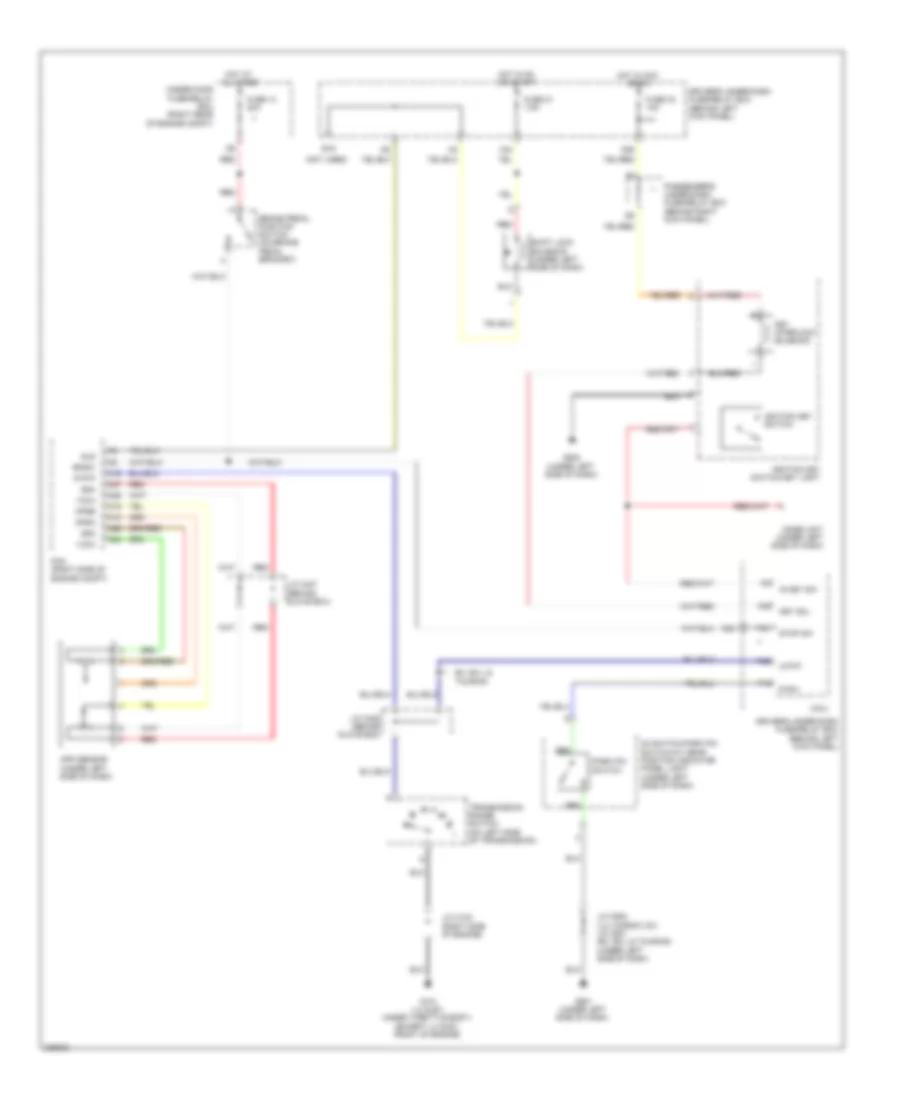
SHIFT INTERLOCK
Shift Interlock Wiring Diagram for Honda Odyssey Touring 2010
List of elements for Shift Interlock Wiring Diagram for Honda Odyssey Touring 2010:
- (behind glove box)
- (behind left kick panel)
- (not used)
- A16
- A18
- A19
- A24
- A25
- A26
- A27
- App sensor (under left side of dash)
- Apsa
- Apsb
- Atp-p
- Bksw
- Brake pedal position switch (on brake pedal bracket)
- D3 switch/park pin switch/a/t gear position indicator panel light (under left side of dash)
- Driver's under-dash fuse/relay box
- Driver's under-dash fuse/relay box (behind left kick panel)
- E16
- Ex, ex-l & touring
- Fuse 13 20a
- Fuse 21 7.5a
- Fuse 32 10a
- G101 (lx & ex: under throttle body) (except lx & ex: front of engine)
- G501 (under left side of dash)
- G502 (under left side of dash)
- Hot at all times
- Hot in acc or on
- Hot in on or start
- Ig key sw
- Ignition key switch
- Ignition key switch/key light
- Imoes unit (under left side of dash)
- J/c c102 (right side of engine)
- J/c c405 (behind glove box)
- J/c c407
- J/c c502 (lx; canada; dx) j/c c501 (ex, ex-l & touring) (under left side of dash)
- Key interlock solenoid
- Key sol
- Micu
- N26
- N36
- Of engine compt)
- P-pin
- P13
- P29
- P30
- Park pin switch
- Passenger's under-dash fuse/relay box (behind right kick panel)
- Pcm (right side of engine compt)
- Red
- Sg3
- Sg4
- Shift lock solenoid (under left side of dash)
- Sls
- Stop sw
- Transmission range switch (on left side of transmission)
- Under-hood fuse/relay box (right rear
- Vcc3
- Vcc4
- X34
 English