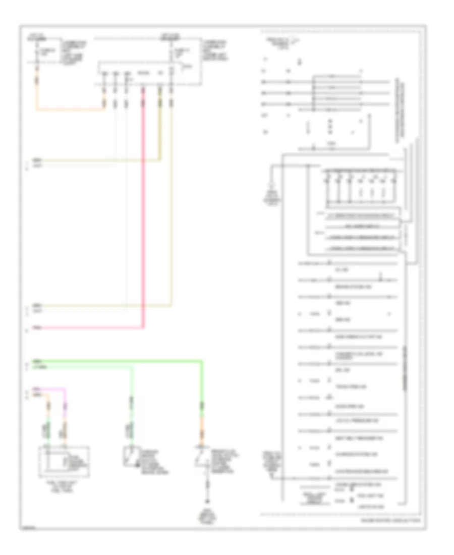
INSTRUMENT CLUSTER
Instrument Cluster Wiring Diagram, DX, GX (1 of 2) for Honda Civic DX 2008

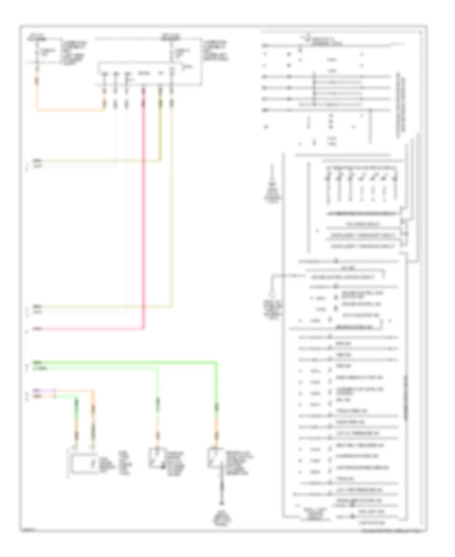
List of elements for Instrument Cluster Wiring Diagram, DX, GX (1 of 2) for Honda Civic DX 2008:
- 10v stabilize circuit
- 5v control circuit
- 5v stabilize circuit/controller area network controller
- Beeper
- Body controller network transceiver
- Brighten switch
- Computer data line system
- Dash lights brightness controller
- Dial brightness control and dimming circuit
- Dimming switch
- Drive circuit
- Driver
- Engine coolant temp. gauge (lcd)
- Engine coolant temp. gauge brightness control and dimming circuit
- Exterior lights system
- Fast controller network transceiver
- Fuel gauge (lcd)
- Fuel gauge brightness control and dimming circuit
- G12
- G401 (behind right side of front bumper)
- G501 (under gauge assembly)
- G503 (under left side of dash)
- G504 (near under- dash junction box)
- Gauge control module (speedo)
- Gauge control module (tach)
- High beam dimming circuit
- High beam ind
- Interior lights system
- J11
- J14
- J19
- J20
- J21
- J22
- K13
- K14
- Lcd
- Lcd back light
- Lcd brightness control and dimming circuit
- Lcd driver
- Left turn signal ind
- Low fuel ind
- Mph/ km/h switch sending
- Multi-informational display (mid) unit
- Pnk
- Pointer brightness control and dimming circuit
- Red
- Right turn signal ind
- Select/ reset switch
- Speedo
- Speedometer (lcd)
- Speedometer brightness control and dimming circuit
- Tach
- Tachometer
- To a/t gear position ind drive circuit (diagram 2 of 2)
- To cruise control dimming circuit (diagram 2 of 2)
- To pin 17 (diagram 2 of 2)
- Turn signal/ hazard relay 2
- Under-dash junction box (under left side of dash)
- Warning drive circuit
- Washer fluid level switch (canada)
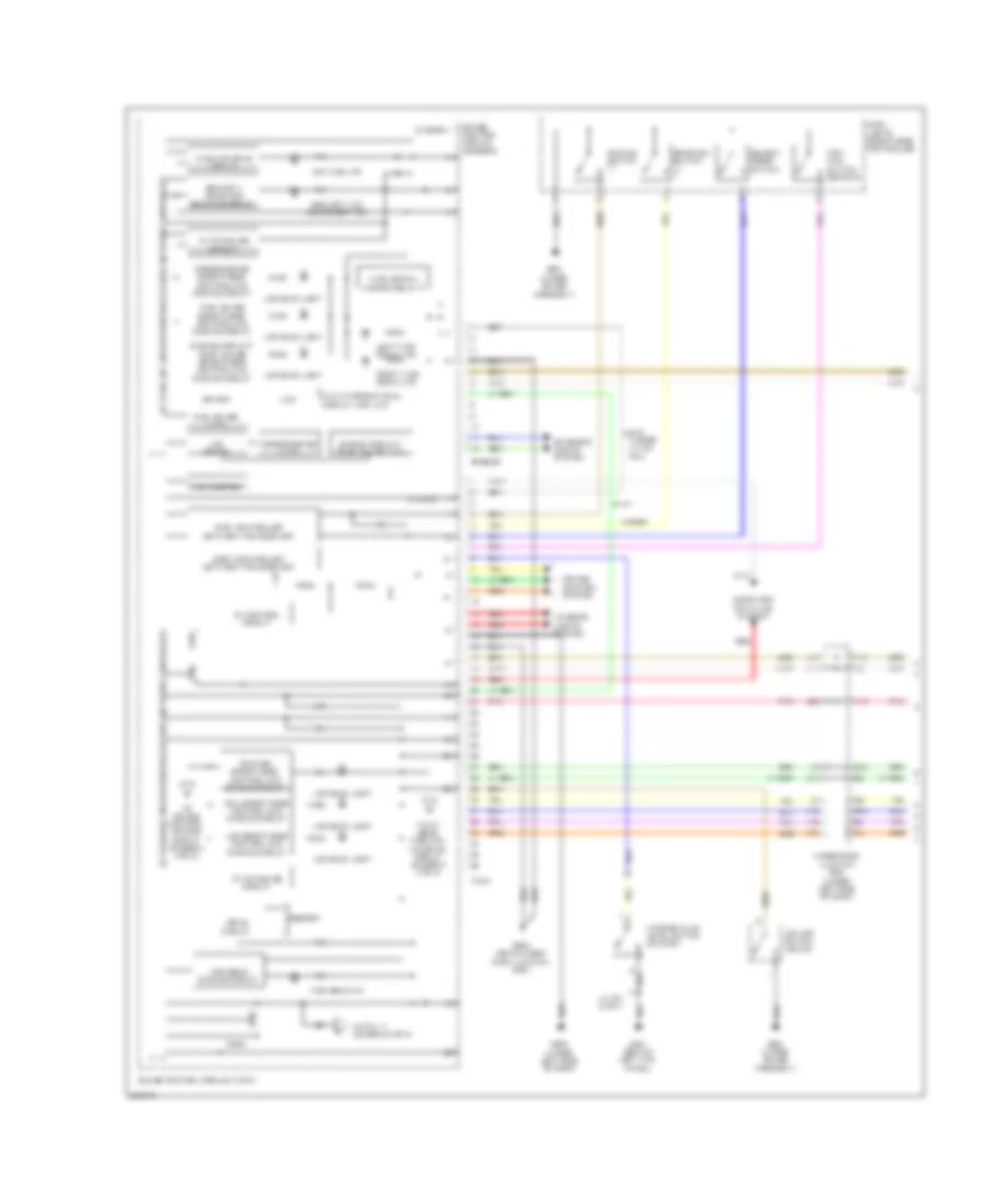
Instrument Cluster Wiring Diagram, DX, GX (2 of 2) for Honda Civic DX 2008
List of elements for Instrument Cluster Wiring Diagram, DX, GX (2 of 2) for Honda Civic DX 2008:
- 5v stabilize circuit/controller
- A/t gear position dimming circuit
- A/t gear position ind drive circuit
- Abs ind
- Area network controller
- B-can
- Brake fluid level switch (on brake master cylinder reservoir)
- Brake system ind
- Charging system ind
- Compulsory turning-off circuit
- Compulsory turning-on circuit
- Door open ind
- Drl ind
- Fail-safe circuit
- Fog light ind
- From 10v stabilize circuit (diagram 1 of 2)
- From pin 16 (diagram 1 of 2)
- From pin 18 c (diagram 1 of 2)
- Fuel gauge sending unit
- Fuel tank unit (in top of fuel tank)
- Fuse 10 7.5a
- Fuse 23 10a
- G401 (behind left kick panel)
- Gauge control module (tach)
- Hot at all times
- Hot in on or start
- Ig1
- Immobilizer system ind
- Lights on ind
- Low oil pressure ind
- Maintenance required ind
- Micu
- Mil ind
- P10
- Parking brake switch (at base of parking brake lever)
- Pnk
- Seat belt reminder ind
- Side airbag cut-off ind
- Small light dimming circuit
- Srs ind
- Trunk open ind
- Under-dash fuse/relay box (under left end of dash)
- Under-hood fuse/relay box (left side of engine compt)
- Vbu
- Warning drive circuit
- Washer fluid level ind (canada)
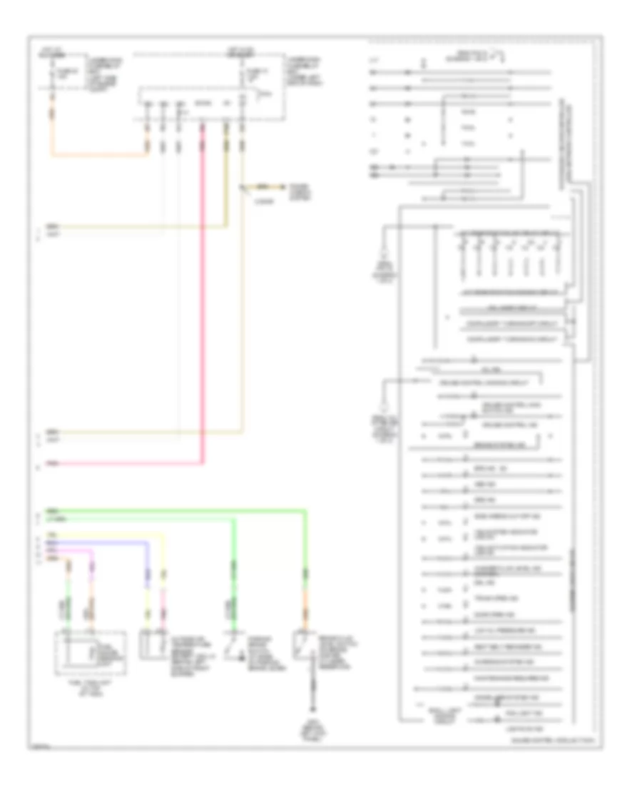
Instrument Cluster Wiring Diagram, EX, LX, SI & EX-L (1 of 2) for Honda Civic DX 2008
List of elements for Instrument Cluster Wiring Diagram, EX, LX, SI & EX-L (1 of 2) for Honda Civic DX 2008:
- (2 door)
- 10v stabilize circuit
- 4 door
- 5v control circuit
- 5v stabilize circuit/controller area network controller
- Beeper
- Body controller network transceiver
- Brighten switch
- Computer data line system
- Cruise control system
- Dash lights brightness controller
- Dial brightness control and dimming circuit
- Dimming switch
- Drive circuit
- Driver
- Engine coolant temp. gauge (lcd)
- Engine coolant temp. gauge brightness control and dimming circuit
- Exterior lights system
- Fast controller network transceiver
- Fuel gauge (lcd)
- Fuel gauge brightness control and dimming circuit
- G12
- G13
- G401 (behind left kick panel)
- G501 (under gauge assembly)
- G503 (under left side of dash)
- G504 (near under- dash junction box)
- Gauge control module (speedo)
- Gauge control module (tach)
- High beam dimming circuit
- High beam ind
- Interior lights system
- J11
- J14
- J16
- J19
- J20
- J21
- J22
- K13
- K14
- Lcd
- Lcd back light
- Lcd brightness control and dimming circuit
- Lcd driver
- Left turn signal ind
- Low fuel ind
- Lx, ex & ex-l
- Mph/ km/h switch sending
- Multi-informational display (mid) unit
- Pnk
- Pointer brightness control and dimming circuit
- Red
- Right turn signal ind
- Security ind (usa except dx)
- Security indicator blinking circuit
- Select/ reset switch
- Si & 2 door: lx, ex ex-l
- Speedo
- Speedometer (lcd)
- Speedometer brightness control and dimming circuit
- Tach
- Tachometer
- To a/t gear position ind drive circuit (diagram 2 of 2)
- To cruise control dimming circuit (diagram 2 of 2)
- To pin 17 (diagram 2 of 2)
- Turn signal/ hazard relay 2
- Under-dash junction box (under left side of dash)
- Vsa off switch (usa si)
- Warning drive circuit
- Washer fluid level switch (canada)
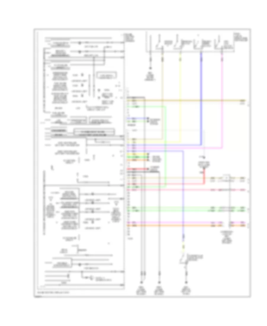
Instrument Cluster Wiring Diagram, EX, LX, SI & EX-L (2 of 2) for Honda Civic DX 2008
List of elements for Instrument Cluster Wiring Diagram, EX, LX, SI & EX-L (2 of 2) for Honda Civic DX 2008:
- (si)
- 2 door
- 5v stabilize circuit/controller
- A/t gear position dimming circuit
- A/t gear position ind drive circuit
- Abs ind
- Area network controller
- B-can
- Brake fluid level switch (on brake master cylinder reservoir)
- Brake system ind
- Charging system ind
- Compulsory turning-off circuit
- Compulsory turning-on circuit
- Cruise control dimming circuit
- Cruise control ind
- Cruise control main switch ind
- Door open ind
- Drl ind
- Eps ind
- Fail-safe circuit
- Fog light ind
- From 10v stabilize circuit (diagram 1 of 2)
- From pin 16 (diagram 1 of 2)
- From pin 18 c (diagram 1 of 2)
- Fuel gauge sending unit
- Fuel tank unit (in top of tank)
- Fuse 10 7.5a
- Fuse 23 10a
- G401 (behind left kick panel)
- Gauge control module (tach)
- Hot at all times
- Hot in on or start
- Ig1
- Immobilizer system ind
- Lights on ind
- Low oil pressure ind
- Maintenance required ind
- Micu
- Mil ind
- Outside air temperature sensor (except usa lx) (behind left side of front bumper)
- P10
- Parking brake switch (at base of parking brake lever)
- Pnk
- Power window system
- Seat belt reminder ind
- Side airbag cut-off ind
- Small light dimming circuit
- Srs ind
- Trunk open ind
- Under-dash fuse/relay box (under left end of dash)
- Under-hood fuse/relay box (left side of engine compt)
- Vbu
- Vsa activation indicator (usa si)
- Vsa system indicator (usa si)
- Warning drive circuit
- Washer fluid level ind (canada)
Instrument Cluster Wiring Diagram, Hybrid (1 of 2) for Honda Civic DX 2008
List of elements for Instrument Cluster Wiring Diagram, Hybrid (1 of 2) for Honda Civic DX 2008:
- (asst/chrg) lcd brightness control and dimming circuit
- (odo/trip) lcd brightness control and dimming circuit
- 10v stabilize circuit
- 5v control circuit
- 5v stabilize circuit/controller area network controller
- Beeper
- Body controller network transceiver
- Brighten switch
- Charge/assist gauge
- Computer data lines system
- Cruise control system
- Dash lights brightness controller
- Dial brightness control and dimming circuit
- Dimming switch
- Drive circuit
- Driver
- Engine coolant temp. gauge (lcd)
- Engine coolant temp. gauge brightness control and dimming circuit
- Exterior lights system
- Fast controller network transceiver
- Fuel gauge (lcd)
- Fuel gauge brightness control and dimming circuit
- G12
- G401 (behind left kick panel)
- G501 (under gauge assembly)
- G503 (under left side of dash)
- G504 (under left side of dash)
- Gauge control module (speedo)
- Gauge control module (tach)
- High beam dimming circuit
- High beam ind
- Ima battery level gauge
- Interior lights system
- J11
- J14
- J19
- J20
- J21
- J22
- K13
- K14
- Lcd
- Lcd back light
- Lcd driver
- Left turn signal ind
- Low fuel ind
- Mph/ km/h switch sending
- Multi-informational display (mid) unit
- Pnk
- Pointer brightness control and dimming circuit
- Red
- Right turn signal ind
- Security ind
- Security indicator blinking circuit
- Select/ reset switch
- Speedo
- Speedometer (lcd)
- Speedometer brightness control and dimming circuit
- Tach
- Tachometer
- To a/t gear position ind drive circuit (diagram 2 of 2)
- To cruise control dimming circuit (diagram 2 of 2)
- To pin 17 (diagram 2 of 2)
- Turn signal/ hazard relay 2
- Under-dash junction box (under left side of dash)
- Warning drive circuit
- Washer fluid level switch (canada)
Instrument Cluster Wiring Diagram, Hybrid (2 of 2) for Honda Civic DX 2008
List of elements for Instrument Cluster Wiring Diagram, Hybrid (2 of 2) for Honda Civic DX 2008:
- 5v stabilize circuit/controller
- A/t gear position dimming circuit
- A/t gear position ind drive circuit
- Abs ind
- Area network controller
- Auto idle stop ind
- B-can
- Brake fluid level switch (on brake master cylinder reservoir)
- Brake system ind
- Charging system ind
- Compulsory turning-off circuit
- Compulsory turning-on circuit
- Cruise control dimming circuit
- Cruise control ind
- Cruise control main switch ind
- Door open ind
- Drl ind
- Eps ind
- Fail-safe circuit
- Fog light ind
- From 10v stabilize circuit (diagram 1 of 2)
- From pin 16 (diagram 1 of 2)
- From pin 18 (diagram 1 of 2)
- Fuel gauge sending unit
- Fuel tank unit (inside fuel tank)
- Fuse 10 7.5a
- Fuse 23 10a
- G401 (behind left kick panel)
- Gauge control module (tach)
- Hot at all times
- Hot in on or start
- Ig1
- Immobilizer system ind
- Lights on ind
- Low oil pressure ind
- Low tire pressure ind
- Maintenance required ind
- Micu
- Mil ind
- P10
- Parking brake switch (at base of park lever)
- Pnk
- Seat belt reminder ind
- Side airbag cut-off ind
- Small light dimming circuit
- Srs ind
- Tpms ind
- Trunk open ind
- Under-dash fuse/relay box (under left end of dash)
- Under-hood fuse/relay box (left rear of engine compt)
- Vbu
- Warning drive circuit
- Washer fluid level ind (canada)