POWER DISTRIBUTION
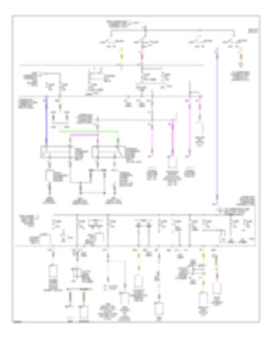
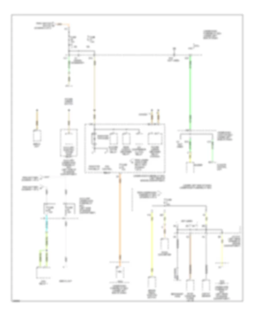
Power Distribution Wiring Diagram, Except Hybrid (1 of 3) for Honda Civic DX 2008

List of elements for Power Distribution Wiring Diagram, Except Hybrid (1 of 3) for Honda Civic DX 2008:
- (4dr) (2dr)
- (honda accessory)
- (left side of engine compartment) under-hood fuse/relay box
- (m/t) (a/t)
- (not used)
- (option connector)
- (w/ gx) (w/o gx)
- (w/ si) (w/o si)
- (w/o gx) (w/ gx)
- +b d/l
- +b day lt/smart
- +b h/l hi main
- +b h/l lo main
- +b haz
- +b horn
- +b intr lt
- +b rr fog
- +b small
- 100a
- 30a
- 30a (w/o si) 40a (w/ si)
- 40a
- 50a
- 60a
- 70a
- A/c compressor clutch relay
- A/c condenser fan relay
- A10
- Abs modulator control unit (w/o si) vsa modulator control unit (w/ si)
- Alternator
- Battery
- Blower motor relay
- Brake pedal position switch
- Ceiling light
- E10
- E22
- E38
- Electrical load detector (eld) unit (usa) (canada: si)
- Eps control unit (si, canada: dx-g & m/t)
- Etcs control relay
- F13
- F31 g16
- From battery a (diagram 1 of 3)
- From multi-fuse 1 e (diagram 1 of 3)
- Front individual map lights (lx, gx, ex, ex-l, si)
- Fuse (not used)
- Fuse 10a
- Fuse 15a
- Fuse 20a
- Fuse 20a (honda accessory)
- Fuse 20a 30a
- Fuse 30a 40a
- Fuse 40a
- Fuse 7.5a
- Fuse 7.5a (usa)
- G18
- G19
- G20
- G21
- Hazard warning switch
- Ignition coil relay
- Micu
- Moonroof control unit (ex, ex-l, si, canada: lx moonroof)
- Multi- fuse 1
- Multi- fuse 2
- Multi- fuse 3
- Multi- fuse 4
- Pgm-fi main relay 1
- Pgm-fi sub-relay
- Radiator fan relay
- Rear window defogger relay
- Red
- Starter
- Starter solenoid
- Stereo amplifier (ex, ex-l, si, 2-dr & 4-dr)
- To ignition switch (diagram 2 of 3)
- To under-dash fuse/relay box (diagram 2 of 3)
- To under-dash fuse/relay box, fuse 15 (diagram 3 of 3)
- To under-dash fuse/relay box, fuse 28 & 29 (diagram 2 of 3)
- To under-hood fuse/relay box, multi-fuse 3 (diagram 1 of 3)
- To under-hood fuse/relay box, multi-fuse 4 (diagram 1 of 3)
- Tpms control unit (usa)
- Trunk light
- Under- dash fuse/ relay box (under left end of dash)
- Under-dash fuse/relay box (under left end of dash)
- Vbu
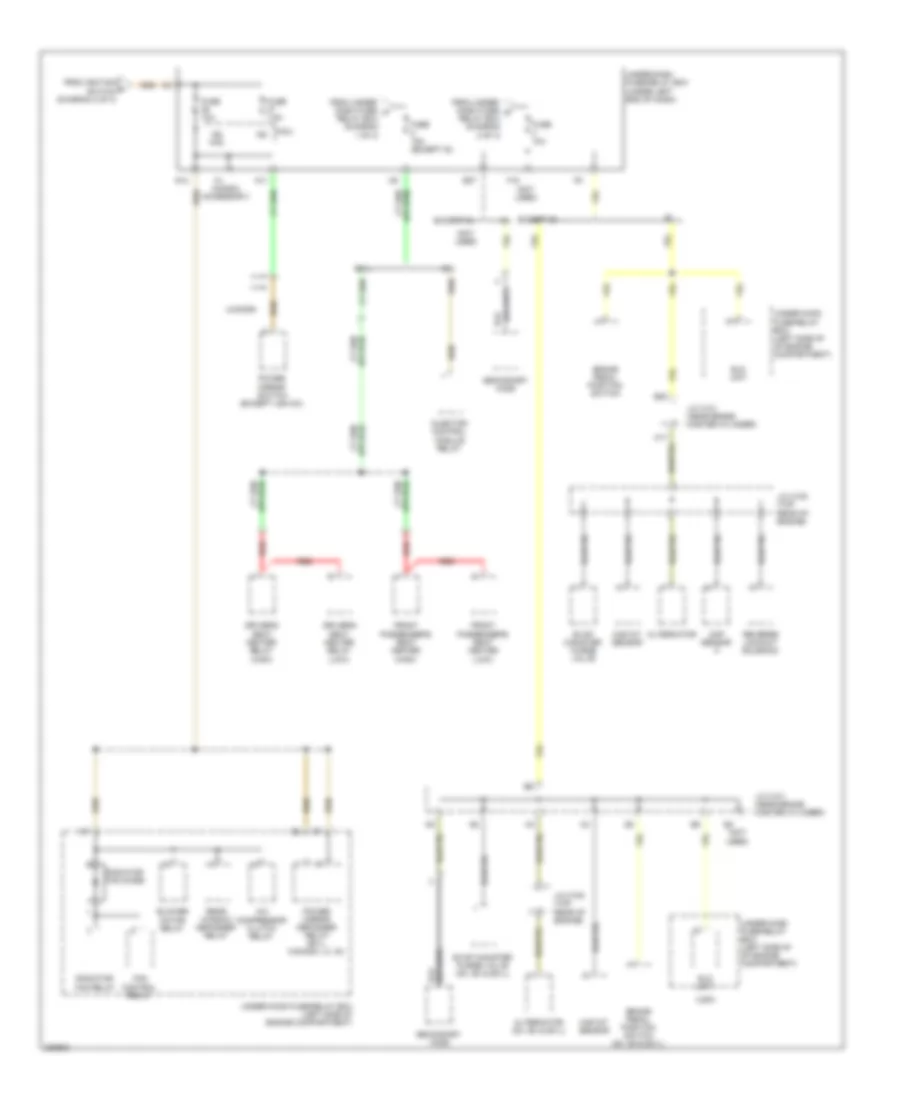
Power Distribution Wiring Diagram, Except Hybrid (2 of 3) for Honda Civic DX 2008
List of elements for Power Distribution Wiring Diagram, Except Hybrid (2 of 3) for Honda Civic DX 2008:
- (a/t)
- (diagram 1 of 3)
- (not used)
- (under left end of dash) under-dash fuse/relay box
- (w/o si) (w/ si)
- 2-dr
- 4-dr
- A14
- A22
- Abs modulator- control unit (w/o si) vsa modulator- control unit (w/ si)
- Acc
- Acc key lock
- Audio unit (except navigation) navigation unit (usa: ex, ex-l, si)
- B17
- Back-up light switch (m/t)
- C36
- Console accessory power socket (ex, ex-l, si) 2-dr & 4-dr)
- Console accessory power socket relay (ex, ex-l & si)
- D16
- E24
- E28
- E30
- E32
- E35
- Ecm
- Ecm/pcm
- Eps control unit (si, canada: dx-g & m/t)
- Except si
- F16
- F17
- F24
- From under- dash fuse/ relay box (diagram 1 of 3)
- From under-dash fuse/relay box (diagram 1 of 3)
- From under-dash fuse/relay box b
- Front accessory power socket
- Front accessory power socket relay
- Fuse
- Fuse (not used)
- Fuse 10a
- Fuse 15a
- Fuse 30a
- Fuse 7.5a
- G11
- G502 (behind glove box)
- G503 (under left side of dash)
- G601 (front left side of floor)
- Ig1
- Ig1 abs
- Ig1 fuel pump
- Ig1 ods
- Ig1 p/w
- Ig1 srs
- Ig1 wiper
- Ignition key switch
- Ignition switch
- J/c c101 (near brake master cylinder)
- Lock
- Micu
- N12
- Ods unit
- On acc
- Pgm-fi main relay 2 (except gx)
- Power mirror switch (4-door, except usa dx)
- Power window relay
- R17
- Red
- Shift lock solenoid (a/t)
- Start
- Starter cut relay
- Stereo amplifier (2-dr: ex, ex-l, si)
- Stereo amplifier (4-dr: si)
- Sts
- To under-dash fuse/ relay box, fuse 3 (diagram 3 of 3)
- To under-dash fuse/relay box, fuse 36 & 37 (diagram 3 of 3)
- Under-dash fuse/relay box (under left end of dash)
- Under-dash junction box (under left side of dash)
- Yaw-rate lateral acceleration sensor (usa: si)
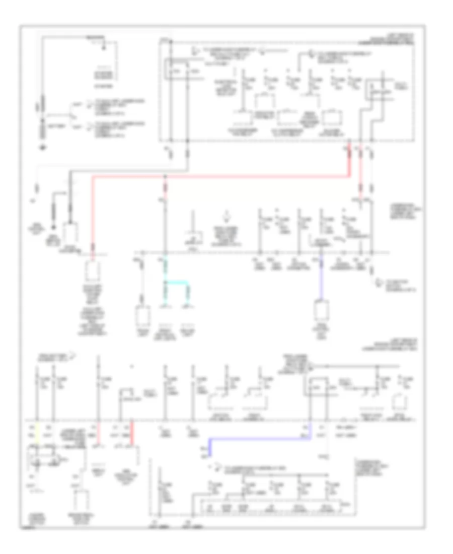
Power Distribution Wiring Diagram, Except Hybrid (3 of 3) for Honda Civic DX 2008
List of elements for Power Distribution Wiring Diagram, Except Hybrid (3 of 3) for Honda Civic DX 2008:
- (4-door)
- (honda accessory)
- (not used)
- (usa)
- A/c compressor clutch relay
- A17
- Alternator
- Alternator (dx, ex & ex-l)
- B22
- Blower motor relay
- Brake pedal position switch
- Brake pedal position switch (gx, ex & ex-l)
- Cmp sensor a
- Driver's seat heater relay (high)
- Driver's seat heater relay (low)
- E27
- Eld unit
- Evap canister purge valve
- Evap canister purge valve (dx, ex & ex-l)
- Ex-l
- Except si
- F15
- Fan control relay
- From ignition f switch (diagram 2 of 3)
- From under- dash fuse/ d relay box (diagram 2 of 3)
- From under- dash fuse/ h relay box (diagram 1 of 3)
- Front passenger's seat heater (high)
- Front passenger's seat heater (low)
- Fuse 10a
- Fuse 15a (except si)
- Fuse 7.5a
- G12
- Ig2
- Ig2 hac
- Injector control module relay
- J/c c101 (near brake master cylinder)
- J/c c105 (top rear of engine)
- Maf/iat sensor
- Micu
- N11
- Power mirror defogger relay (ex-l, canada: lx, si)
- Power mirror switch (except usa dx)
- Radiator fan diode
- Radiator fan relay
- Rear window defogger relay
- Red
- Reverse lockout solenoid
- Secondary ho2s
- Under-dash fuse/relay box (under left end of dash)
- Under-hood fuse/relay box (left side of engine compartment)
- Under-hood fuse/relay box (left side of of engine compartment)
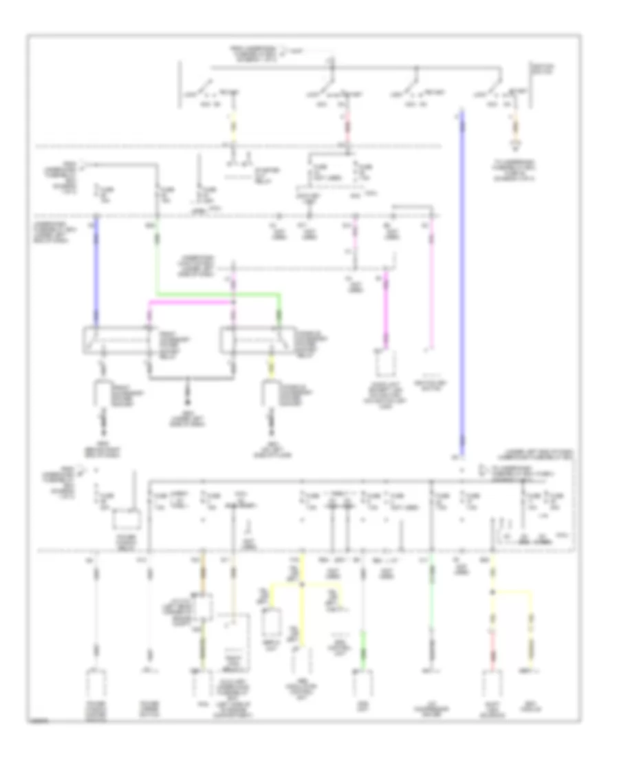
Power Distribution Wiring Diagram, Hybrid (1 of 3) for Honda Civic DX 2008
List of elements for Power Distribution Wiring Diagram, Hybrid (1 of 3) for Honda Civic DX 2008:
- (honda accessory)
- (left rear of engine compartment) under-hood fuse/relay box
- (not used)
- (option connector)
- (under left end of dash) under-dash fuse/ relay box
- +b d/l
- +b day lt/smart
- +b h/l hi main
- +b h/l lo main
- +b haz
- +b horn
- +b intr lt
- +b rr fog
- +b small
- 100a
- 30a
- 40a
- 50a
- 60a
- 70a
- A/c compressor clutch relay
- A/c condenser fan relay
- Abs modulator control unit
- Auxiliary electric water pump relay
- Auxiliary under-hood fuse/relay box (left side of of engine compartment)
- Battery
- Blower motor relay
- Braided
- Brake pedal position switch
- Ceiling light
- D2 red
- Dc-dc converter
- E22
- Electrical load detector (eld) unit
- Eps control unit
- Etcs cntrl relay
- F13
- F31
- From battery a (diagram 1 of 3)
- From under- dash fuse/ relay box, fuse 29 (diagram 2 of 3)
- From under- hood fuse/ relay box, multi-fuse 1 b (diagram 1 of 3)
- Front individual map lights
- Fuse
- Fuse (not used)
- Fuse 10a
- Fuse 15a
- Fuse 20a
- Fuse 20a (honda accessory)
- Fuse 20a (not used)
- Fuse 30a
- Fuse 40a
- Fuse 7.5a
- Fuse 7.5a (usa)
- G1 red
- G16
- G18
- G19
- G20
- G21
- G904 (behind ipu lid)
- Hazard warning switch
- Ignition coil relay
- Micu
- Multi- fuse 2
- Multi- fuse 3
- Multi- fuse 4
- Multi-fuse 1
- Pgm-fi main relay 1
- Pgm-fi sub-relay
- Radiator fan relay
- Rear window defogger relay
- Red
- Servo unit
- Starter
- Starter solenoid
- To auxiliary under-hood fuse/relay box, fuse 61 (diagram 3 of 3)
- To auxiliary under-hood fuse/relay box, fuse 63 (diagram 3 of 3)
- To ignition switch (diagram 2 of 2)
- To under-dash fuse/relay box (diagram 2 of 3)
- To under-hood fuse/relay box multi-fuse 3 & 4 (diagram 1 of 3)
- To under-hood fuse/relay box, fuse 23 (diagram 3 of 3)
- Tpms control unit (usa)
- Trunk light
- Under-dash fuse/relay box (under left end of dash)
Power Distribution Wiring Diagram, Hybrid (2 of 3) for Honda Civic DX 2008
List of elements for Power Distribution Wiring Diagram, Hybrid (2 of 3) for Honda Civic DX 2008:
- (diagram 1 of 3)
- (not used)
- (under left end of dash) under-dash fuse/relay box
- A/c compressor driver
- A14
- A22
- A29
- Abs modulator- control unit
- Acc
- Acc key lock
- Audio unit (except usa navigation) navigation unit (usa)
- Auxiliary under-hood fuse/relay box (left side of of engine compartment)
- B17
- Bcm module
- C36
- Console accessory power socket
- Console accessory power socket relay
- D16
- E24
- E28
- E30
- E32
- E35
- Eps control unit
- F16
- F17
- F24
- From under-dash fuse/relay box (diagram 1 of 3)
- From under-dash fuse/relay box c
- Front accessory power socket
- Front accessory power socket relay
- Fuse (not used)
- Fuse 10a
- Fuse 15a
- Fuse 20a
- Fuse 30a
- Fuse 7.5a
- G11
- G502 (behind right end of dash)
- G503 (under left side of dash)
- G601 (on left side of floor)
- Ig1
- Ig1 abs
- Ig1 fuel pump
- Ig1 ods
- Ig1 p/w
- Ig1 srs
- Ig1 wiper
- Ignition key switch
- Ignition switch
- J/c c101 (left rear corner of engine compt)
- Lock
- Micu
- N12
- Ods unit
- On acc
- Pcm
- Pgm-fi main relay 2
- Power mirror switch
- Power window master switch
- Power window relay
- R17
- Red
- Servo unit
- Shift lock solenoid
- Start
- Starter cut relay
- Sts
- To under-dash fuse/relay box, fuse 3 (diagram 3 of 3)
- To under-dash fuse/relay box, fuse 36 (diagram 3 of 3)
- Under-dash fuse/relay box (under left end of dash)
- Under-dash junction box (under left side of dash)
Power Distribution Wiring Diagram, Hybrid (3 of 3) for Honda Civic DX 2008
List of elements for Power Distribution Wiring Diagram, Hybrid (3 of 3) for Honda Civic DX 2008:
- (diagram 2 of 3)
- (honda accessory)
- (not used)
- (under left end of dash) under-dash fuse/relay box
- A/c compressor clutch relay
- Auxiliary electric water pump relay
- Auxiliary under-hood fuse/relay box (left side of engine compartment)
- Auxiliary under-hood fuse/relay box (left side of of engine compartment)
- Blower motor relay
- Brake pedal position switch
- Buzzer
- Canada
- Climate control unit
- Dc-dc converter
- E27
- Eld unit
- Evap canister purge valve
- F15
- Fan control
- From battery g (diagram 1 of 3)
- From battery h (diagram 1 of 3)
- From ignition switch k
- From under- hood fuse/ relay box (diagram 1 of 3)
- From under-dash fuse/relay box (diagram 2 of 3)
- Fuse 10a
- Fuse 15a
- Fuse 7.5a
- G12
- Hac
- Ig2
- J/c c101 (left rear corner of engine compartment)
- Maf/iat sensor
- Mcm relay 1
- Micu
- N11
- Power mirror defogger relay (canada)
- Power mirror switch
- Q16
- R19 (not used)
- Radiator fan diode
- Radiator fan relay
- Rear window defogger relay
- Relay
- Secondary ho2s
- Servo unit
- Under-dash fuse/relay box (under left end of dash)
- Under-dash junction box (under left side of dash)
- Under-hood fuse/relay box (left rear of engine compartment)
- Vbu