ANTI-LOCK BRAKES
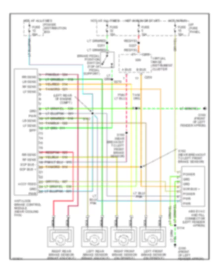
Anti-lock Brake Wiring Diagrams for Lincoln Continental 1998
List of elements for Anti-lock Brake Wiring Diagrams for Lincoln Continental 1998:
- (left rear of engine compt)
- A bus -
- Abs evac and fill connector (left fender apron)
- Accy feed
- Anti-lock brake control module (near cooling fan)
- B bus +
- Bpp
- Brake pedal position switch (top of pedal support)
- C255
- C256
- Fuse 10a
- Fuse 15a
- Fuse 60a
- G100 (front of left fender apron)
- Grd
- Hot at all times
- Hot in run
- Hot in run or start
- I/p fuse panel
- Ign
- Left front brake sensor (on spindle)
- Left rear brake sensor (brake knuckle)
- Lf sens
- Lr sens
- Nca
- Power
- Power distribution box
- Pwr
- Red/pnk
- Rf sens
- Right front brake sensor (on spindle)
- Right rear brake sensor (brake knuckle)
- Rr sens
- S114
- S117
- S160 (near breakout to left front brake sensor)
- S162 (near breakout to left front brake sensor)
- S227
- S251
- S270
- Scp bus +
- Scp bus -
- Scr bus +
- Virtual image instrument cluster
 English