POWER DISTRIBUTION
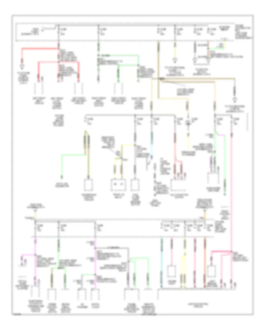
Power Distribution Wiring Diagram (1 of 4) for Lincoln Continental 1998

List of elements for Power Distribution Wiring Diagram (1 of 4) for Lincoln Continental 1998:
- (eng compt harn, in anti-lock brake control module breakout) s117
- (i/p harn, near left kick panel) s226
- (near breakout to dual auxiliary relay box) s142
- (rear body harn, center front of trunk) s434
- Abs evac and fill connector
- Air bag electronic crash sensor
- Anti-lock brake control module
- Battery
- Blower motor relay
- C522
- C524
- C601
- C811
- Compressor relay
- Dual auxiliary relay box
- From fuse 5 (diagram 1 of 4)
- From fuse 8 (diagram 1 of 4)
- Fuse 10a
- Fuse 15a
- Fuse 20a
- Fuse 30a
- Fuse 40a
- Fuse 60a
- Fuse position
- Generator/ voltage regulator
- Hi beam relay
- High speed cooling fan relay
- Horn relay
- I/p fuse panel (below left side of dash)
- Left front door module
- Left rear window switch
- Low speed cooling fan relay
- Mega fuse 175a
- Not used
- Pcm power relay
- Pnk
- Power distribution box (left side of engine compartment)
- Rear window defrost relay
- Red
- Right front window switch
- Right rear window switch
- Starter motor assembly
- To fuse 4 (diagram 2 of 4)
- To fuse 5 (diagram 1 of 4)
- To fuse 7 (diagram 1 of 4)
- Vehicle dynamic module
Power Distribution Wiring Diagram (2 of 4) for Lincoln Continental 1998
List of elements for Power Distribution Wiring Diagram (2 of 4) for Lincoln Continental 1998:
- (body harn, near subwoofer amp breakout) s406
- (i/p harn, near brake on/off switch breakout) s251
- (i/p harn, near i/p fuse panel breakout)
- (rear body harn, near trunk lid relay breakout)
- Brake pedal position switch
- Breakout)
- C207
- C208
- C256
- C268
- C269
- C275
- C348
- C362
- C456
- Cd changer
- Data link connector
- Digital clock
- Electronic automatic temperature control module
- From fuse 4 (diagram 1 of 4)
- From power distribution box (fuse 10) (diagram 2 of 4)
- From s239 (diagram 2 of 4)
- Front control unit (radio)
- Fuel filler door release switch
- Fuse
- Fuse 10a
- Fuse 15a
- Fuse 20a
- Fuse 30a
- Fuse 40a
- Fuse 60a
- G200 (left kick panel)
- I/p cigar lighter or console cigar lighter
- I/p fuse panel (below left side of dash)
- Left front 2 way power lumbar switch
- Left front heated seat module
- Left front seat module
- Light sensor/ amplifier
- Lighting control module
- Multi-function switch
- Nca
- Not used
- Phone support electronics module
- Pnk
- Power distribution box (left side of engine compartment)
- Power point
- Powertrain control module
- Red
- Remote emergency satellite cellular unit module
- Right front 2 way power lumbar switch
- Right front heated seat module
- Right front seat control switch
- S211 (near breakout to rescu control)
- S239
- S241 (i/p harn, in i/p fuse panel breakout)
- S252 (i/p harn, behind left side of dash)
- S253 (i/p harn, near elect temp control module breakout)
- S259 (near breakout to digital clock)
- S274 (near breakout to heated seat switch assembly)
- S313 (body harn, left side of vehicle, near driver's seat)
- S316 (body harn, near power lumbar switch breakout)
- S322 (body harn, near power lumbar sw breakout)
- S416 (near breakout to rear window defrost relay)
- S441
- Speed control deac switch
- Starter relay
- Subwoofer amplifier
- Tan
- Tan/red
- Terminates in harness
- To i/p fuse panel (fuse 26) (diagram 2 of 4)
- To i/p fuse panel (fuse 39) (diagram 3 of 4)
- To i/p fuse panel (fuses 1, 7, 13, 19 & 25) (diagram 2 of 4)
- To ignition switch (diagram 3 of 4)
- Trunk lid relay
- Virtual image instrument cluster
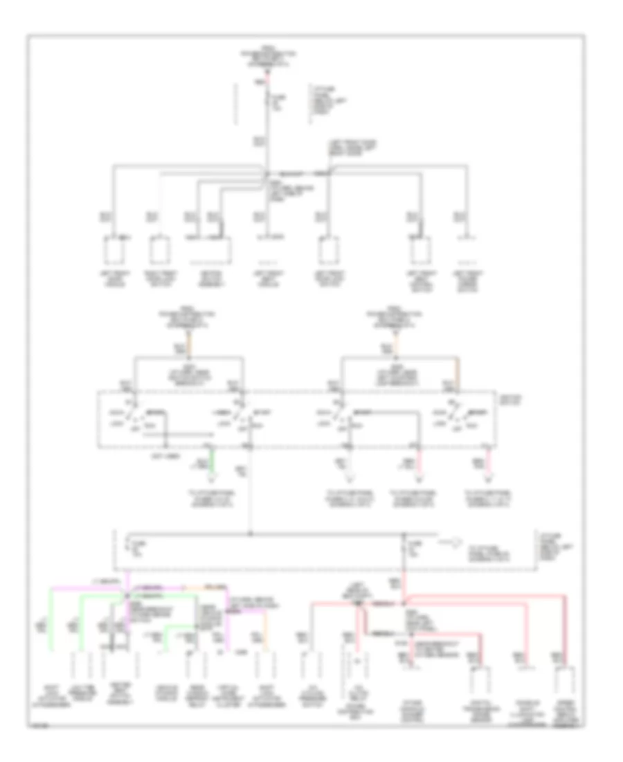
Power Distribution Wiring Diagram (3 of 4) for Lincoln Continental 1998
List of elements for Power Distribution Wiring Diagram (3 of 4) for Lincoln Continental 1998:
- (i/p harn, behind left side of dash) s268
- (left front door harn, inside left front door)
- (left rear of eng compt) s156
- (near breakout to heated oxygen sensor)
- (near vehicle dynamic module) s419
- (not used)
- A/c clutch relay
- A/c cycling pressure switch
- Acc
- C256
- C342
- C524
- Console shift illumination lamp (5 passenger)
- Digitial transmission range sensor
- From power distribution box (fuse 1) (diagram 2 of 4)
- From power distribution box (fuse 3) (diagram 2 of 4)
- From power distribution box (fuse 4) (diagram 2 of 4)
- Fuse 10a
- Fuse 15a
- Heated seat switch assembly
- I/p fuse panel (below left side of dash)
- Ignition switch
- Intake manifold runner control
- Keypad switch assembly
- Left front door lock switch
- Left front door module
- Left front power mirror switch
- Left front seat control switch
- Left front seat module
- Lock
- Low tire pressure module
- Nca
- Off
- Power distribution box
- Rear window defrost relay
- Red
- Right front door lock switch
- Run
- S129
- S202 (i/p harn, near ignition switch breakout)
- S229 (i/p harn, near left courtesy lamp breakout)
- S254 (i/p harn, behind left side of dash)
- S264 (i/p harn, near left kick panel)
- S502
- Shift lock actuator (5 passenger)
- Shift lock actuator (6 passenger)
- Speed control servo/ amplifier assembly
- Start
- To i/p fuse panel (fuse 40) (diagram 4 of 4)
- To i/p fuse panel (fuses 23 & 29) (diagram 4 of 4)
- To i/p fuse panel (fuses 3, 9, 15 & 21) (diagram 4 of 4)
- To i/p fuse panel (fuses 4 & 16) (diagram 4 of 4)
- To i/p fuse panel (fuses 5, 11, & 17) (diagram 4 of 4)
- Vehicle dynamic module
- Virtual image instrument cluster
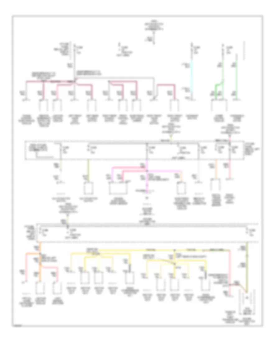
Power Distribution Wiring Diagram (4 of 4) for Lincoln Continental 1998
List of elements for Power Distribution Wiring Diagram (4 of 4) for Lincoln Continental 1998:
- (near breakout to abs evac and fill connector)
- (near breakout to center high mount stop lamp) s415
- (near breakout to park brake switch)
- (near ign coil no 3) s112
- (near ign coil no 7)
- (not used)
- Air bag electronic crash sensor
- Blower motor relay
- C277
- Digital trans- mission range sensor
- Ebs evac and fill connector
- Electronic automatic temperature control module
- Electronic day/night mirror
- From i/p fuse panel (fuse 34) (diagram 3 of 5)
- From igntion switch (acc/run) (diagram 3 of 4)
- From igntion switch (run) (diagram 3 of 4)
- From igntion switch (run/start) (diagram 3 of 4)
- From igntion switch (start) (diagram 3 of 4)
- Front control unit (radio)
- Fuse 10a
- Fuse 15a
- Fuse 30a
- Fuse position
- I/p fuse
- I/p fuse panel (below left side of dash)
- Ignition coils no 1
- Ignition coils no 2
- Ignition coils no 3
- Ignition coils no 4
- Ignition coils no 5
- Ignition coils no 6
- Ignition coils no 7
- Ignition coils no 8
- Left front door lock switch
- Left rear window switch
- Light sensor/ amplifier
- Lighting control module
- Moonroof switch
- Multifunction switch
- Nca
- Panel (below left side of dash)
- Passive anti- theft transceiver module
- Pcm power relay
- Phone support electronics module
- Power distribution box
- Radio interference capacitor no 1
- Radio interference capacitor no 2
- Red/
- Remote emergency satellite cellular module
- Right front door lock switch
- Right front window switch
- Right rear window switch
- S130
- S132 (left rear of eng compt)
- S170
- S267
- S314 (left side of driver's seat)
- Side of dash)
- Virtual image instrument cluster
- Windshield wiper motor
- Wiper control module