ENGINE PERFORMANCE
4.6L
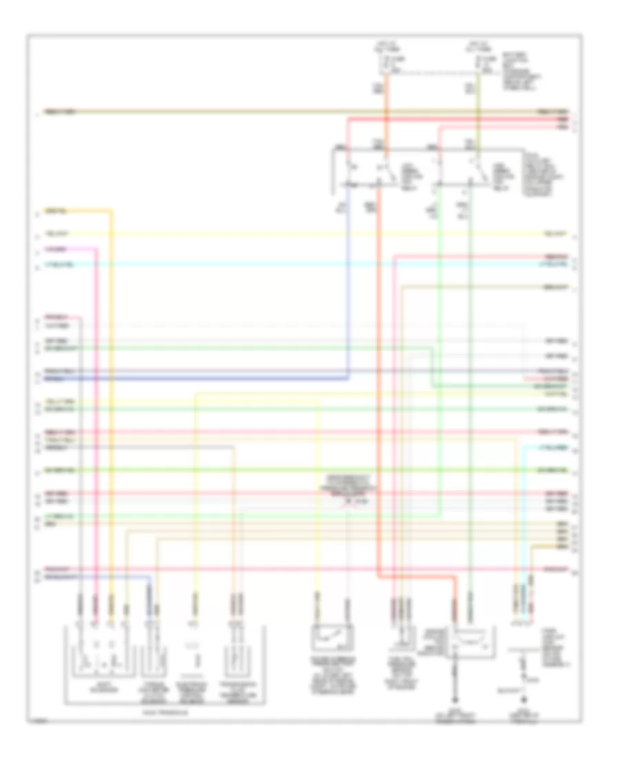
4.6L, Engine Performance Wiring Diagrams (1 of 4) for Lincoln Continental 2001

List of elements for 4.6L, Engine Performance Wiring Diagrams (1 of 4) for Lincoln Continental 2001:
- (at bottom left of dash) data link connector (dlc)
- (left rear of engine compt) s132
- A/c clutch
- A/c system
- Ckp sensor (+)
- Ckp sensor (-)
- Cooling fan hi
- Cooling fan lo
- Crankshaft position (ckp) sensor (on lower right side of engine)
- Crankshaft position sensor shield
- Digital transmission range (dtr) sensor (on left side of engine, on top of transaxle)
- Dtr sensor tr1
- Dtr sensor tr2
- Dtr sensor tr4
- Ect sensor
- Egr sol
- Egr vacuum regulator (evr) solenoid (on front of eng, near left side of front valve cover)
- Engine coolant temperature (ect) sensor (on top left front of engine)
- Eprom power
- Fuel pump
- Fuel sender
- G121 (center of firewall)
- Ground
- Ho2s 12
- Iat input
- Ignition coil 1
- Ignition coil 3
- Ignition coil 4
- Ignition coil 5
- Ignition coil 6
- Ignition coils
- Intake air temperature (iat) sensor (on top center of engine)
- Knock sensor
- Maf return
- Nca
- Ohms
- Powertrain control module (pcm) (on top right side of firewall, under splash shield)
- Psp switch
- R n
- Radio interference capacitor 1 (in engine compt, right of master cylinder)
- S100
- S103
- S160 (near breakout to left front brake sensor)
- S162
- Scp bus (+)
- Scp bus (-)
- Shift sol a
- Shift sol b
- Shift sol c
- Tcc sol
- Tft input
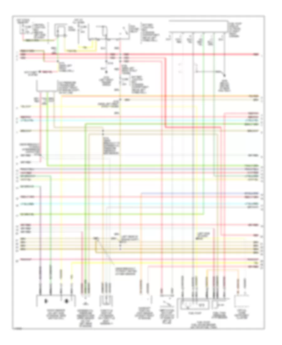
4.6L, Engine Performance Wiring Diagrams (2 of 4) for Lincoln Continental 2001
List of elements for 4.6L, Engine Performance Wiring Diagrams (2 of 4) for Lincoln Continental 2001:
- (near breakout to differential pressure feedback egr sensor)
- Ax4n transaxle
- Battery junction box (in engine compartment, above left wheelwell)
- Dual auxilary relay box (center of engine compt, on upper radiator support)
- Electronic pressure control solenoid
- Engine cooling fan (behind radiator)
- Fuel rail pressure sensor (on top right front of engine)
- Fuse 30a
- Fuse 60a
- G100 (on left front fender apron)
- G121 (center of firewall)
- High speed cooling fan relay
- Hot at all times
- Low speed cooling fan relay
- Mass airflow (maf) sensor (on air intake assembly)
- Power steering pressure (psp) switch (in lower left rear of engine compt, on power steering gear)
- Red
- Red/pnk
- S100
- S126
- Shift solenoids
- Tan/ red
- Torque converter clutch solenoid
- Transmission fluid temperature sensor
4.6L, Engine Performance Wiring Diagrams (3 of 4) for Lincoln Continental 2001
List of elements for 4.6L, Engine Performance Wiring Diagrams (3 of 4) for Lincoln Continental 2001:
- (left rear of engine compt) s131
- (left side of dash) s232
- (near breakout to front heated oxygen sensor)
- (near breakout to radio interference capacitor) s122
- A/c pressure transducer (in right front of engine compt, on a/c line)
- Anti-theft system
- Battery junction box (in engine compartment, above left wheelwell)
- Camshaft position (cmp) sensor (on right front of engine)
- Central junction box (behind left side of dash)
- Differential pressure feedback egr (dpfe) sensor (on top left rear of engine)
- Front strut tower)
- Fuel pump
- Fuel pump module (in trunk, at right front corner)
- Fuel pump/ fuel gauge sender (on top of fuel tank)
- Fuel tank pressure (ftp) sensor
- Fuse 10a
- Fuse 30a
- G100 (left front fender apron)
- G408 (below center of rear pkg tray)
- Hot at all times
- Hot in run or start
- Inertia fuel shut-off (ifs) switch (at base of
- Knock sensor (on left side of engine, near ignition coil)
- Left "b" pillar)
- Nca
- Pcm diode
- Pcm power relay
- Red
- Red/pnk
- S124 (near breakout to differential pressure feedback egr sensor)
- S148
- S155 (near left red
- S158 (near left front strut tower)
- S170 (near left front wheelwell)
- S172
- Throttle position (tp) sensor (on throttle body assembly)
- Virtual image instrument cluster
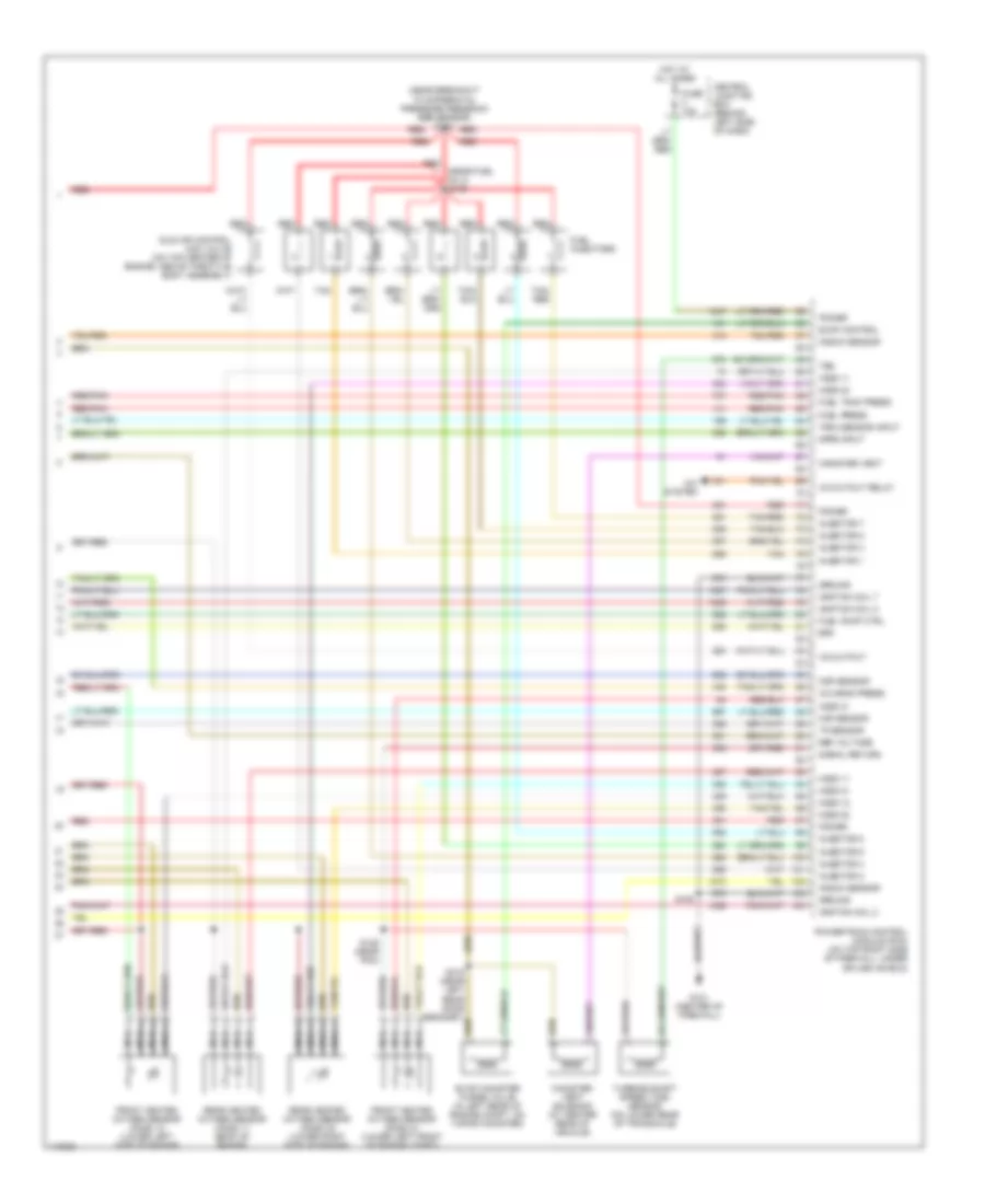
4.6L, Engine Performance Wiring Diagrams (4 of 4) for Lincoln Continental 2001
List of elements for 4.6L, Engine Performance Wiring Diagrams (4 of 4) for Lincoln Continental 2001:
- (near breakout to differntial pressure feedback egr sensor) s134
- (near fuel inj 3) s146
- A/c cutout relay
- A/c head press
- A/c system
- Canister vent
- Canister vent solenoid (at center rear of vehicle)
- Central junction box (behind left side of dash)
- Cmp sensor
- Dpfe input
- Epc
- Evap canister purge valve (in left rear of engine compt, on vapor canister)
- Evap control
- Front heated oxygen sensor (h02s) 12 (lower left side of engine)
- Front heated oxygen sensor (h02s) 21 (lower left front of engine compt)
- Fuel injectors
- Fuel press
- Fuel pump ctrl
- Fuel tank press
- Fuse 10a
- G121 (center of firewall)
- Ground
- Ho2s 11
- Ho2s 12
- Ho2s 21
- Ho2s 22
- Hot at all times
- Iac output
- Idle air control (iac) valve (on top center of engine, above throttle body assembly)
- Ignition coil 2
- Ignition coil 7
- Ignition coil 8
- Injector 1
- Injector 2
- Injector 3
- Injector 4
- Injector 5
- Injector 6
- Injector 7
- Injector 8
- Knock sensor
- Maf sensor
- Nca
- Power
- Powertrain control module (pcm) (on top right side of firewall, under splash shield)
- Rear heated oxygen sensor (h02s) 11 (back of engine)
- Rear heated oxygen sensor (h02s) 22 (lower right side of engine)
- Red
- Red/pnk
- Ref voltage
- S100
- S125 (near pcm)
- S315 (near left rear door grommet)
- Signal return
- Tan
- Tan/ red
- Tan/red
- Tp sensor
- Tr3a sensor input
- Tss
- Turbine shaft speed (tss) sensor (on lower rear of transaxle)