SUPPLEMENTAL RESTRAINTS
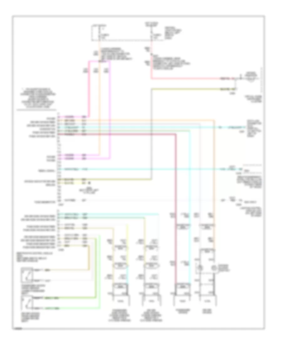
Supplemental Restraint Wiring Diagram for Lincoln Continental 2001
List of elements for Supplemental Restraint Wiring Diagram for Lincoln Continental 2001:
- 1 pin in-line connector, left side of vehicle, left side of driver seat) s314
- Air bag indicator
- Air bag indicator driver
- Air bag sliding contact
- C206
- C255
- C326
- C327
- C449
- Central junction box (below left side of dash)
- Data link connector (dlc) (partial) (at bottom c251
- Diagnostics
- Driver air bag
- Driver air bag crash sensor (under driver seat)
- Driver air bag feed
- Driver air bag return
- Driver side air bag (w/side airbags) resistor a (w/o side airbags)
- Driver side air bag feed
- Driver side air bag return
- Driver side sensor feed
- Driver side sensor return
- Fuse 5 10a
- Fuse 9 10a
- G900 (bottom of left "a" pillar)
- Ground
- Hot in run
- Hot in run or start
- Left of dash)
- Lighting control module (lcm) (on left side of dash)
- Nca
- Pass air bag feed
- Pass air bag return
- Pass side air bag feed
- Pass side air bag return
- Pass side sensor feed
- Pass side sensor return
- Passenger air bag
- Passenger air bag crash sensor (under passenger seat)
- Passenger side air bag (w/side airbags) resistor b (w/o side airbags)
- Pin shorting bar is engaged when module connector is disconnected from harness (shorting bar is connected between pins: 3-4, 6-7, 20-21 conn. c327 2-3 & 5-6 conn. c326)
- Power
- Rcm
- Rcm input
- Remote emergency satellite cellular unit (rescu) module (in right rear of trunk)
- Rescu signal
- Restraints control module (rcm) (between seats, below center console)
- S227 (14a005 harness, near breakout to 10 pin in-line connector, left side of dash, near a pillar breakout to eatc module)
- Shorting bar
- Tone generator
- Virtual image instrument cluster
 English