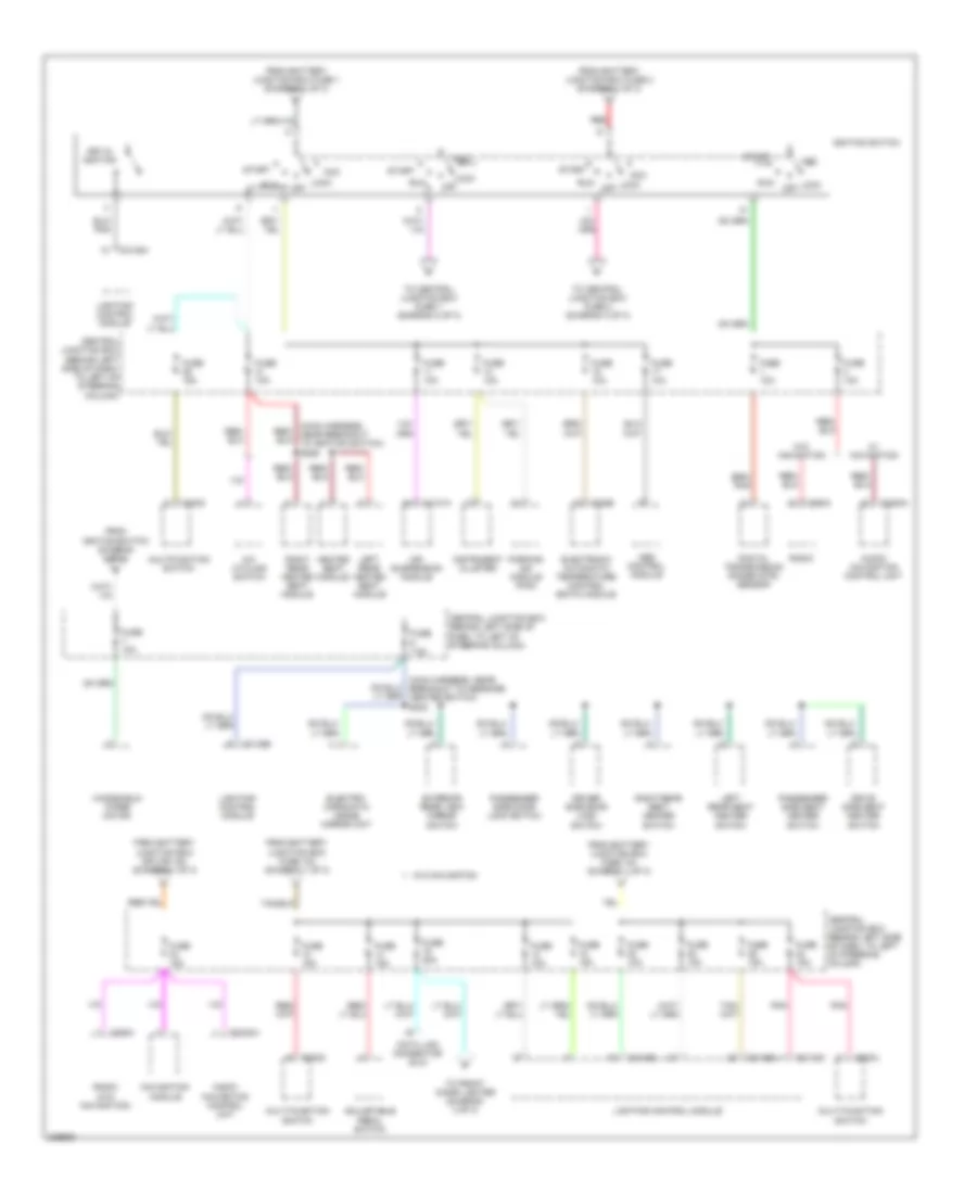
POWER DISTRIBUTION
Power Distribution Wiring Diagram (1 of 3) for Lincoln Town Car Designer 2006

List of elements for Power Distribution Wiring Diagram (1 of 3) for Lincoln Town Car Designer 2006:
- (at right of engine compt) battery junction box (bjb)
- (in body main harness, near breakout to c2131a) s213
- (in body main harness, near breakout to c2131a) s279
- (in body main harness, near breakout to c4197) s460
- (in body main harness, near breakout to c4211a) s453
- (in body main harness, near breakout to c501b) s501
- (in body main harness, near breakout to c681) s602
- (in dash panel to headlamp junction harness, near breakout to battery junction box (bjb)) s169
- (in dash panel to headlamp junction harness, near breakout to c139) s180
- (main body, near breakout to c211) s245
- (starter motor relay & battery ground, near breakout to fusible link a) s162
- A/c clutch relay
- Abs control module
- Air suspension compressor relay
- Air suspension module
- Battery
- Battery junction box (bjb) (at right of engine compt)
- Blower motor relay
- Brake pedal position switch
- C102a
- C102b
- C175b
- C197a
- C2131a
- C341b
- C4081d
- C4211a
- C501b
- Central junction box (behind left side of dash, to left of steering column)
- Driver door module
- Driver seat module
- Engine cooling fan module
- From a fuse 16 (diagram 1 of 3)
- From b fuse 104 (diagram 1 of 3)
- Fuel door release switch
- Fuel pump relay
- Fuse 10a
- Fuse 15a
- Fuse 20a
- Fuse 25a
- Fuse 30a
- Fuse 40a
- Fuse 50a
- Generator
- Harness, near breakout to g102)
- Heated seat module
- Horn relay
- Ignition coils relay
- Left front lumbar adjust switch
- Left rear heated seat module
- Navigation system amplifier (w/ navigation)
- Powertrain control module (pcm)
- Rear window defrost relay
- Red
- Right front lumbar adjust switch
- Right rear heated seat module
- Roof opening panel unit
- S136 (in starter motor relay & battery ground harness, near breakout to fusible link a)
- Starter motor
- Starter relay
- Subwoofer amplifier (w/o navigation)
- To central junction box fuse 10 (diagram 2 of 3)
- To central junction box fuse 20 (diagram 2 of 3)
- To central junction box fuse 21 (diagram 3 of 3)
- To central junction box fuse 33 (diagram 2 of 3)
- To fuse 107 (diagram 1 of 3)
- To fuse 12 (diagram 1 of 3)
- To fuse 601 (diagram 3 of 3)
- To ignition switch (diagram 2 of 3)
- To left rear power point (diagram 3 of 3)
- To power point (diagram 3 of 3)
- To right rear power point (diagram 3 of 3)
- To s200 (diagram 3 of 3)
- Trunk pull-down module
- Windshield wiper motor
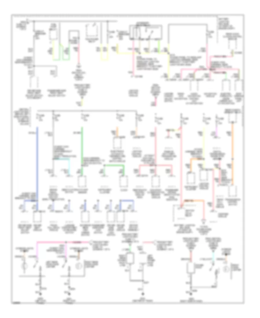
Power Distribution Wiring Diagram (2 of 3) for Lincoln Town Car Designer 2006
List of elements for Power Distribution Wiring Diagram (2 of 3) for Lincoln Town Car Designer 2006:
- (main harness, near breakout to ignition switch) s255
- (main harness, near breakout to message center switch) s232
- A/c cycling switch
- Abs control module
- Acc
- Adjustable pedal switch
- Air suspension module
- Audio/ navigation control unit
- C202a
- C202c
- C2131a
- C2145a
- C2145b
- C2145c
- C2145d
- C2253a
- C228b
- C290a
- Central junction box (behind left side of dash, to left of steering column)
- Data link connector (dlc)
- Digital transmission range (dtr) sensor
- Drive side seat heater switch
- Driver side door lock switch
- Electro- chromatic inside mirror unit
- Electronic automatic temperature control (eatc) module
- Exterior rear view mirror switch
- From battery junction box fuse 1 (diagram 1 of 3)
- From battery junction box fuse 103 (diagram 1 of 3)
- From battery junction box fuse 104 (diagram 1 of 3)
- From battery junction box fuse 2 (diagram 1 of 3)
- From battery junction box splice 180 (diagram 1 of 3)
- From ignition switch (diagram 2 of 3)
- Fuse 10a
- Fuse 15a
- Fuse 20a
- Fuse 7.5a
- Heated seat module
- Ignition switch
- Instrument cluster
- Key in ignition
- Left rear heated seat module
- Left rear seat heater switch
- Lighting control module
- Lock
- Multi-function switch
- Multifunction switch
- Navigation module
- Off
- Parking aid module (pam)
- Passenger side door lock switch
- Passenger side seat heater switch
- Pnk
- Radio
- Radio (w/o navigation)
- Red
- Right rear heated seat module
- Right rear seat heater switch
- Run
- Start
- To central junction box fuse 2 (diagram 3 of 3)
- To central junction box fuse 7 (diagram 2 of 3)
- To front cigar lighter (diagram 3 of 3)
- W/ navigation
- W/o navigation
- Windshield wiper motor
Power Distribution Wiring Diagram (3 of 3) for Lincoln Town Car Designer 2006
List of elements for Power Distribution Wiring Diagram (3 of 3) for Lincoln Town Car Designer 2006:
- (at right footwell, forward of "a" pillar) s217
- (in body main harness, near breakout to c211)
- (in body main harness, near breakout to c219) s306
- (in body main harness, near breakout to c248) (early production) s263
- (in body main harness, near breakout to c523)
- (in main harness, near breakout to c220a) s209
- (main harness, near breakout to ignition switch) s219
- Accessory delay relay
- Audio/ navigation control unit (w/ navigation)
- Autolamp sensor
- Battery junction box (bjb) (at right of engine compt)
- Brake pedal position switch (early production)
- C2145a
- C2145b
- C2253a
- C228b
- C290a
- C310a
- C314c
- C3160b
- C4081c
- C501b
- C504b
- Central junction box (behind left side of dash, to left of steering column)
- Circuit breaker 20a
- Clock
- Compass module
- Deactivator switch
- Digital transmission range (dtr) sensor
- Driver door module
- Driver seat module
- Driver side door lock switch
- Driver side front seat adjust switch
- Driver side front seat adjust switch (w/o memory)
- Electro- chromatic inside mirror unit (w/ navigation)
- Electronic automatic temperature control (eatc) module
- Exterior rear view mirror switch
- From battery junction box fuse 111 (diagram 1 of 3)
- From battery junction box fuse 113 (diagram 1 of 3)
- From battery junction box fuse 115 (diagram 1 of 3)
- From battery junction box fuse 13 (diagram 1 of 3)
- From battery junction box fuse 5 (diagram 1 of 3)
- From c fuse 118 (diagram 1 of 3)
- From central junction box fuse 16 (diagram 2 of 3)
- From ignition coil relay (diagram 3 of 3)
- From ignition switch (diagram 2 of 3)
- Front cigar lighter
- Fuel pump relay
- Fuse 10a
- Fuse 30a
- G202 (right side of dash)
- G209 (left kick panel)
- G301 (right kick panel)
- G404 (center of trunk)
- Ignition coils relay
- Instrument cluster
- Interior lights system
- Keypad switch assembly
- Left rear door cigar lighter
- Left rear power point (lwb)
- Lighting control module
- Luggage compartment lid release switch
- Master window adjust switch
- Navigation module
- Occupant classification sensor module
- Passenger air bag deactivation (pad) indicator
- Passenger side door lock switch
- Passenger side front seat adjust switch
- Passive anti-theft transceiver module
- Pcm power diode
- Pcm power relay
- Pnk
- Power point
- Radio (w/o navigation)
- Rear audio/ climate control module
- Rear window defrost relay
- Restraints control module (rcm)
- Right rear door cigar lighter
- Right rear power point (lwb)
- Roof opening panel unit
- S168 (in dash panel to headlamp junction harness, near breakout to battery junction box (bjb))
- S170 (in dash panel to headlamp junction harness, near breakout to battery junction box (bjb))
- S200 (in body main, near breakout to c211)
- S271
- S298
- S337
- S502
- S700
- S800
- To pcm power diode (diagram 3 of 3)
- Transmission control switch
- Trunk pull- down module
- Trunk pull-down module