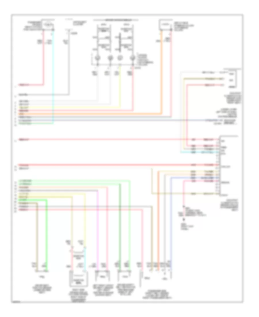
SUPPLEMENTAL RESTRAINTS
Supplemental Restraints Wiring Diagram (1 of 2) for Lincoln Town Car Designer 2006

List of elements for Supplemental Restraints Wiring Diagram (1 of 2) for Lincoln Town Car Designer 2006:
Supplemental Restraints Wiring Diagram (2 of 2) for Lincoln Town Car Designer 2006
List of elements for Supplemental Restraints Wiring Diagram (2 of 2) for Lincoln Town Car Designer 2006: