AIR CONDITIONING
3.8L
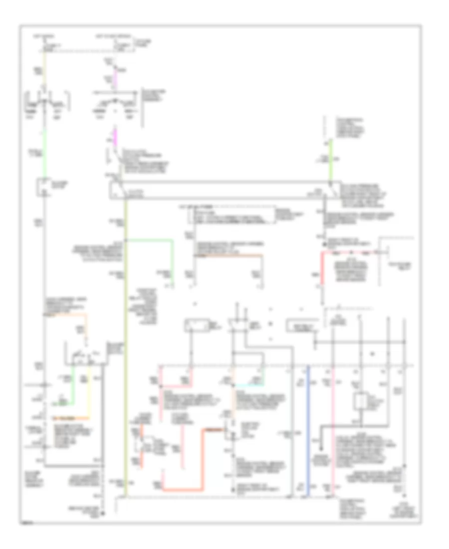
3.8L, A/C Wiring Diagram for Ford Mustang GT 1998

List of elements for 3.8L, A/C Wiring Diagram for Ford Mustang GT 1998:
- (behind center of dash) g206
- (main harness, near breakout to air bag diagnostic connector) s213
- (not used)
- .5 ohms
- 1.3 ohms
- A/c clutch control
- A/c clutch cycling pressure switch (right rear corner of engine compartment, on a/c accumulator)
- A/c clutch field coil
- A/c high pressure cutout/fan switch (lower right front of engine compartment, on a/c line, right of belt tensioner)
- A/c-heater control assembly
- Blower motor
- Blower motor resistor assembly (behind right side of dash, in a/c-heater plenum)
- Blower motor switch
- Constant control relay module (ccrm) (inside right front fender, behind air filter housing)
- Def
- Edf relay
- Edf relay control
- Electric cooling fan motor
- Engine compartment fuse box
- Fan c.b. 30a
- Floor
- Fuse 17 30a
- Fuse 6 15a
- G100 (left front of engine compartment)
- G101 (right front of engine compartment)
- Hot at all times
- Hot in acc or run
- Hot in run
- I/p fuse panel
- Max
- Mix
- Nca
- Norm
- Off
- Pcm power relay
- Pnk/
- Powertrain control module (pcm) (behind right kick panel)
- S102 (engine control sensor harness, near breakout to octane adjust plug)
- S104 (dash panel to headlamp junction harness, near breakout to g101)
- S115 (engine control sensor harness, near breakout to right front brake sensor)
- S119 (engine control sensor harness, near breakout to a/c high pressure cutout/fan switch)
- S122 (engine control sensor harness, in breakout to electric cooling fan motor)
- S201 (main harness, near breakout to ground g206)
- S226
- Thermal limiter
- Vent
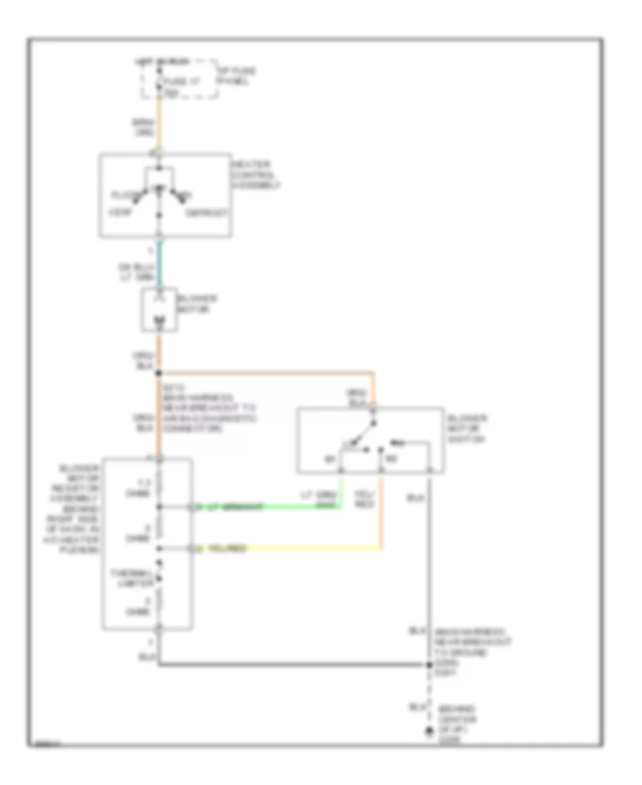
Heater Wiring Diagram for Ford Mustang GT 1998
List of elements for Heater Wiring Diagram for Ford Mustang GT 1998:
- (behind center of i/p) g206
- .5 ohms
- 1.3 ohms
- Blower motor
- Blower motor resistor assembly (behind right side of dash, in a/c-heater plenum)
- Blower motor switch
- Defrost
- Floor
- Fuse 17 30a
- Heater control assembly
- Hot in run
- I/p fuse panel
- Mix
- Off
- S213 (main harness, near breakout to air bag diagnostic connector)
- Thermal limiter
- Vent
4.6L
4.6L, A/C Wiring Diagram for Ford Mustang GT 1998
List of elements for 4.6L, A/C Wiring Diagram for Ford Mustang GT 1998:
- (4.6l-2v, engine control harness, near breakout to in-line connector, right rear of engine compartment) (4.6l-4v, engine control harness, in breakout to intake manifold runner control)
- (behind center of dash) g206
- (engine control sensor harness, near breakout to octane adjust plug) s102
- (engine control sensor harness, near breakout to right front brake sensor) s100
- (main harness, near breakout to air bag diagnostic connector) s213
- (right front of engine compartment) g101
- (w/high current fuse panel) (w/o high current fuse panel)
- .5 ohms
- 1.3 ohms
- 30a c.b.
- A/c clutch cycling pressure switch (right rear corner of engine compartment, on a/c accumulator)
- A/c clutch control
- A/c clutch field coil
- A/c high pressure cutout/fan switch (lower right front of engine compartment, on a/c line, above air cleaner housing)
- A/c-heater control assembly
- Blower motor
- Blower motor resistor assembly
- Blower motor resistor assembly (behind right side of dash, in a/c-heater plenum)
- Blower motor switch
- Clutch switch
- Constant control relay module (ccrm) (inside right front fender, behind air filter housing)
- Def
- Edf relay
- Edf relay control
- Electric cooling fan motor
- Engine compartment fuse box
- Engine controls system
- Fan fuse 50a 60a
- Fan switch
- Floor
- Fuse 17 30a
- Fuse 6 15a
- G100 (left front of engine compartment)
- Hedf relay
- High curent fuse panel
- Hot at all times
- Hot in acc or run
- Hot in run
- I/p fuse panel
- Max
- Mix
- Norm
- Off
- Pcm power relay
- Pnk/
- Powertrain control module (pcm) (behind right kick panel)
- Red
- S115 (engine control sensor harness, near breakout to right front brake sensor)
- S116 (engine control sensor harness, near breakout to right front brake sensor)
- S119 (engine control sensor harness, near breakout to a/c high pressure cutout/fan switch)
- S122 (engine control sensor harness, near breakout to a/c high pressure cut/out fan switch)
- S140 (engine control sensor harness, near breakout to a/c high pressure cut/out fan switch)
- S149
- S201 (main harness, near breakout to ground g206)
- S226
- Thermal limiter
- Vent
- W/high current fuse panel
- W/o high current fuse panel
Heater Wiring Diagram for Ford Mustang GT 1998
List of elements for Heater Wiring Diagram for Ford Mustang GT 1998:
- (behind center of i/p) g206
- .5 ohms
- 1.3 ohms
- Blower motor
- Blower motor resistor assembly (behind right side of dash, in a/c-heater plenum)
- Blower motor switch
- Defrost
- Floor
- Fuse 17 30a
- Heater control assembly
- Hot in run
- I/p fuse panel
- Mix
- Off
- S213 (main harness, near breakout to air bag diagnostic connector)
- Thermal limiter
- Vent