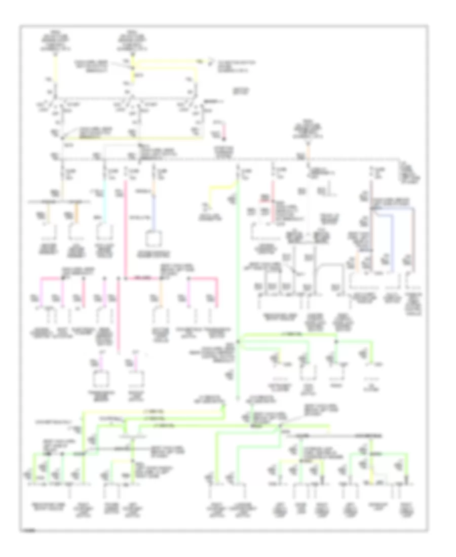
POWER DISTRIBUTION
Power Distribution Wiring Diagram (1 of 3) for Ford Mustang GT 1998

List of elements for Power Distribution Wiring Diagram (1 of 3) for Ford Mustang GT 1998:
- (console panel harn, in fog lamp switch breakout) s305
- (dash panel to headlamp junction harn, near engine compt fuse box breakout)
- (eng cntrl sens harn, near air injection pump breakout) s145
- (radio amp harn, below side of rear seat)
- (radio amp harn, left side of trunk)
- 3.8l
- 4.6l
- Abs fuse 20a
- Abs fuse 40a
- Air injection reaction bypass
- Air injection reaction relay
- Alt fuse 20a
- Amplifier
- Anti-lock brake control module
- Audio fuse 25a
- Auxiliary power socket
- Battery
- Brake pedal position switch
- Brake pressure switch
- C282
- Cig illum fuse 30a
- Cigar lighter
- Constant control relay module
- Conv top fuse 25a
- Daytime running lights module
- Driver's seat control switch
- Drl, fog, horns fuse 20a
- Eec fuse 20a
- Electronic flasher
- Engine compartment fuse box (left side of engine compt)
- Fan circuit breaker 30a
- Fan fuse 60a
- Fog lamps relay (engine compt. fuse box)
- Front speaker subwoofer amplifier
- Fuel pump fuse 20a
- Fuse 15a
- G300 (below rear of center console)
- Generator/ voltage regulator
- Hd lps fuse 50a
- Horn relay (engine compt fuse box)
- Htd bl fuse 40a
- I/p fuse panel (below left side of dash)
- Ign sw fuse 40a
- Int lps fuse 25a
- Left power lumbar seat switch
- Lower relay
- Main light switch
- Power seat fuse 25a
- Powertrain control module
- Premium sound
- Raise relay
- Rear speaker subwoofer amplifier
- Rear window defrost control switch
- Red
- S102
- S108 (eng control sens harn, right side of eng compt)
- S109 (dash panel to headlamp junction harn, lower left side of eng compt)
- S111
- S207 (body main harn, behind right side of dash)
- S212 (radio amp harn, center of dash)
- S303
- S409 (near convert top motor breakout)
- S431
- S432
- Starter motor/ solenoid
- Starter relay
- Super sound
- Tan/ red
- Therm fuse 30a
- To fuse 8 (i/p fuse block) (diagram 2 of 3)
- To ignition switch (diagram 2 of 3)
- To ignition switch (diagram 3 of 3)
- To splice s215 (diagram 2 of 3)
- W/ drl only
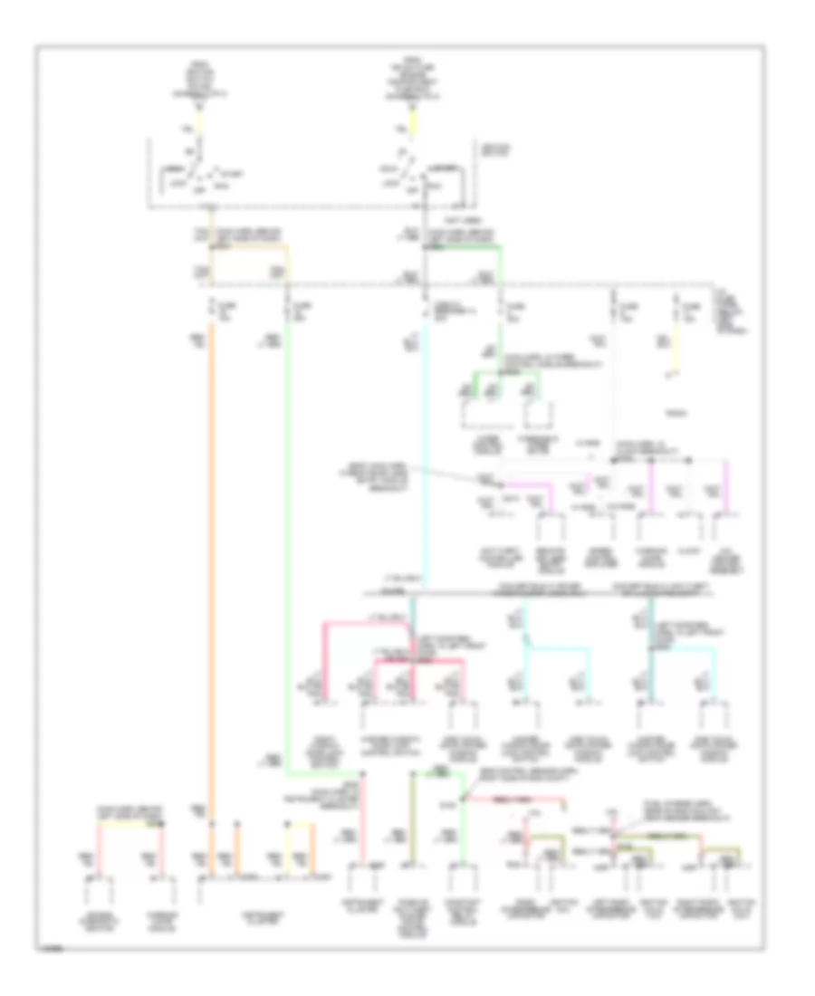
Power Distribution Wiring Diagram (2 of 3) for Ford Mustang GT 1998
List of elements for Power Distribution Wiring Diagram (2 of 3) for Ford Mustang GT 1998:
- (body main harn, behind left side of dash)
- (body main harn, behind left side of dash) s219
- (body main harn, left rear of trunk) s412
- (body main harn, left side of trunk)
- (body main harn, left side of trunk) s410
- (interior lamp harn, center of windshield header) s902
- (main harn, behind left side of dash) s210
- (main harn, near ignition switch breakout)
- (main harn, near lock breakout) s218
- A/c- heater control assembly
- A/t
- Acc
- Air bag diagnostic monitor
- Anti-lock brake control module
- Anti-theft controller module
- Backup lamp switch
- C250
- C257
- C276
- C281
- C401
- C404
- Cd player
- Circuit breaker 12 20a
- Convertible
- Convertible only
- Convertible top switch
- Coupe
- Coupe only
- Data link connector
- Daytime running lamps module
- Dome/ map lamp
- Dome/map lamp
- Electronic flasher
- From hd lps fuse (engine compt fuse box) (diagram 1 of 3)
- From ign sw fuse (engine compt fuse box) (diagram 1 of 3)
- Fuse 10a
- Fuse 15a
- Fuse 20a
- Fuse 30a
- Heater control assembly
- I/p fuse panel (below left side of dash)
- Ignition switch
- Instrument cluster
- Intake manifold runner control
- Left courtesy lamp switch
- Left vanity mirror lamp
- Lock
- Luggage compartment lamp switch
- M/t
- Main light switch
- Master window/ door lock control switch
- Module
- Multi- function switch
- Nca
- Off
- Passive anti- theft system control
- Power mirror switch
- Radio
- Rear window defrost control switch
- Remote/keyless entry module
- Right courtesy lamp switch
- Right vanity mirror lamp
- Right window/ door lock control switch
- Run
- S214 (main harn, near main light switch breakout)
- S215
- S216
- S220 (main harn, near multi- function sw breakout)
- S221 (main harn, near rear window defrost control switch breakout)
- S306
- S411
- S504 (left door window rag harn, in left front door)
- S902
- Shift lock actuator
- Sta
- Start
- Starting/ charging system
- To ignition switch (pin b5) (diagram 3 of 3)
- Transmission control switch
- Transmission range sensor
- Trunk lid release switch
- W/ a/c
- W/ remote keyless entry
- W/ remote/ keyless entry
- W/o a/c
- W/o remote keyless entry
- W/o remote/ keyless entry
Power Distribution Wiring Diagram (3 of 3) for Ford Mustang GT 1998
List of elements for Power Distribution Wiring Diagram (3 of 3) for Ford Mustang GT 1998:
- (body main harn, in remote/keyless entry module breakout)
- (eng control sensor harn, right side of eng compt)
- (fuel charge harn, near on eng coolant temp sender breakout)
- (left door reg harn, in left front door) s505
- (main harn, behind left side of dash) s224
- (main harn, behind left side of dash) s229
- (main harn, in clock breakout) s226
- (main harn, in wiper control module breakout) s225
- (not used)
- 3.8l
- 4.6l
- A/c- heater control assembly
- Acc
- Air bag diagnostic monitor
- Anti-theft controller module
- C250
- C251
- Circuit breaker 14 20a
- Clock
- Constant control relay module
- Convertible w/ anti-theft or illuminated entry
- Convertible w/ power windows/door locks only
- Coupe
- From ign sw fuse (engine compartment fuse box) (diagram 1 fo 3)
- From ignition switch (pin b4) (diagram 2 of 3)
- Fuse 10a
- Fuse 15a
- Fuse 20a
- Fuse 30a
- I/p fuse panel (below left side of dash)
- Ignition coil
- Ignition coils 1 & 2
- Ignition coils 3 & 4
- Ignition switch
- Instrument cluster
- Left radio interference capacitor
- Lock
- Master window/ door lock control switch
- Master window/door lock control switch
- Nca
- Off
- One touch down power window module
- Passive anti-theft system (pats) control module
- Radio
- Radio interference capacitor
- Remote/ keyless entry module
- Right radio interference capacitor
- Right window/ door lock control switch
- Run
- S105
- S228 (main harn, in instrument cluster breakout)
- S413
- Speed control amplifier
- Start
- W/ rke
- W/o rke
- Warning chime module
- Windshield wiper motor
- Wiper control module