AIR CONDITIONING
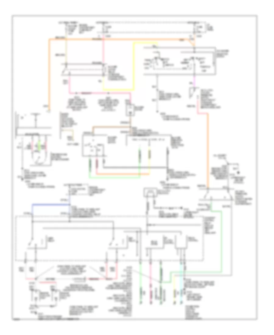
A/C Wiring Diagram, Auto A/C for Ford Taurus G 1997

List of elements for A/C Wiring Diagram, Auto A/C for Ford Taurus G 1997:
- (all except 3.0l 4v)
- (dash panel to headlamp junction harn, near constant control relay module breakout)
- (dash panel to headlamp junction harn, near engine cooling fan 1 breakout)
- (engine cntrl sens harn, near camshaft pos sensor breakout)
- (left front of i/p)
- (main wiring harn, near cigar lighter breakout)
- (main wiring harn, near i/p fuse panel breakout)
- (main wiring harn, near in-car temp sensor breakout)
- (main wiring harn, near pass anti-theft system (pats) breakout)
- (upper right
- (upper right center of cowl)
- 883 or 879
- A/c clutch control
- A/c clutch cycling pressure switch (behind right headlamp)
- A/c clutch field coil
- A/c high pressure switch (front center of engine compartment)
- Ambient temp
- Ambient temperature sensor (center of grille)
- Battery
- Blend door actuator (right side of i/p)
- Blend dr act
- Blower motor
- Blower motor fuse 40a
- Blower motor relay (in engine
- Blower motor speed controller (right side of i/p)
- Blw speed
- C225
- C235
- Center of cowl)
- Compartment fuse/relay box
- Compartment fuse/relay box)
- Constant control relay module (behind left headlamp)
- Cooling fan fuse 40a
- Cycling pres sw
- Data bus
- Data link connector (below steering column)
- Edf relay
- Engine
- Engine compartment fuse/relay box
- Engine cooling fan 1
- Engine cooling fan 2
- Engine cooling fan dropping resistor (inside right front bumper)
- Fuse 15a
- Fuse 5a
- G100 (left front fender)
- G101 (right front fender near coolant overflow reservoir)
- G104 (left front fender, near air cleaner)
- G123
- G206 (lower side of inner glove box frame)
- Ground
- Hedf relay
- Hot at all times
- Hot in run
- I/p fuse panel
- Ign-a/c clutch
- Ignition
- In car temp
- In-car temperature sensor (near climate controls)
- Integrated control panel (center of i/p)
- Nca
- Passive anti-theft system (pats) (center of i/p)
- Pcm input
- Powertrain control module (right rear corner of engine compt)
- Rear control unit (left rear of vehicle)
- Relay control
- Remote climate control module (behind glove box)
- S108 (eng cntrl sens harn, near pcm)
- S109 (3.0l 2v) s160 (3.4l sho) s154 s154 (3.0l 4v) (eng cntrl sens harn, near camshaft pos sensor breakout) (3.0l 4v) s160 (eng cntrl sens harn, near injectors 3 & 4 breakout) (3.4l sho) s109 (eng cntrl sens harn, near injector 3 breakout) (3.0l 2v)
- S131
- S132 (dash panel to headlamp junction harn, near constant control relay module breakout)
- S136
- S145
- S156
- S211
- S213
- S215
- S216 (main wiring harn, near i/p fuse panel breakout)
- S217
- S218
- S219
- S223 (main wiring harn, near electronic flasher breakout)
- Signal return
- Solid state
- Sunload sensor
- Tan
A/C Wiring Diagram, Manual A/C for Ford Taurus G 1997
List of elements for A/C Wiring Diagram, Manual A/C for Ford Taurus G 1997:
- (3.4l sho)
- (all except 3.0l 4v)
- (dash panel to headlamp junction harn, near constant control relay module breakout)
- (dash panel to headlamp junction harn, near engine cooling fan 1 breakout)
- (lower side of
- (main wiring harn, near glove box switch/ lamp breakout)
- (not used)
- (upper right
- (upper right center of cowl)
- 883 or 879
- A/c clutch control
- A/c clutch cycling pressure switch (right front of engine compartment behind headlamp)
- A/c clutch field coil
- A/c high pressure switch (front center of engine compartment)
- A/c-heater
- Blend door actuator (right side of a/c plenum below i/p)
- Blower motor
- Blower motor fuse 40a
- Blower motor relay (in engine compartment fuse/relay box)
- Blower motor switch
- Blower resistor (behind right side of i/p)
- C225
- C235
- Center of cowl)
- Constant control relay module (behind left headlamp)
- Cooling fan fuse 40a
- Def
- Def/flr
- Edf relay
- Engine compartment fuse/relay box
- Engine cooling fan 1
- Engine cooling fan 2
- Engine cooling fan dropping resistor (inside right front bumper)
- Flr
- Flr/vnt
- Fuse 15a
- Fuse 5a
- G101 (right front fender near coolant overflow reservoir)
- G104 (left front fender, near air cleaner)
- G123
- G206
- Hedf relay
- Hot at all times
- Hot in run
- I/p fuse panel
- Inner glove box frame)
- Max
- Norm
- Off
- Pan/flr
- Panel
- Powertrain control module (right rear corner of engine compt)
- Relay control
- S108 (eng cntrl sens harn, near pcm)
- S109 (3.0l 2v)
- S131
- S132 (dash panel to headlamp junction harn, near constant control relay module breakout)
- S136
- S145
- S154 (3.0l 4v) (eng cntrl sens harn, near camshaft pos sensor breakout) (3.0l 4v) s160 (eng cntrl sens harn, near injectors 3 & 4 breakout) (3.4l sho) s109 (eng cntrl sens harn, near injector 3 breakout) (3.0l 2v)
- S156 (engine cntrl sensor harn, near camshaft g123 pos sensor breakout)
- S160
- S210 (dash panel to headlamp harn, left corner of i/p, near headlamp switch)
- S212 (main wiring harn, near cigar lighter breakout)
- S227 (main wiring harn, left corner of i/p, near headlamp switch) (3.0l 4v 0nly)
- S229 (main wiring harn, near glove box switch/ lamp breakout)
- Selector switch
- Solid state
- Temperature control potentiometer
- Vent