ENGINE PERFORMANCE
3.0L
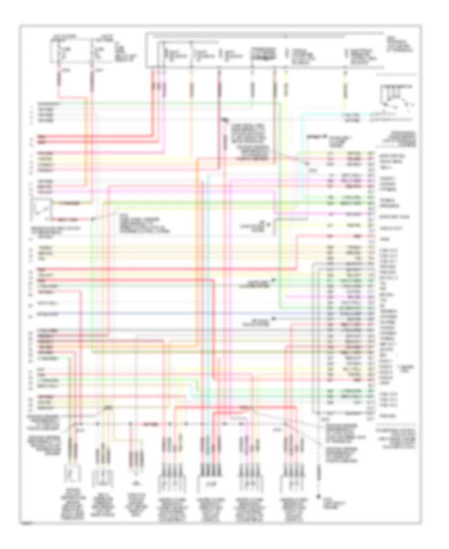
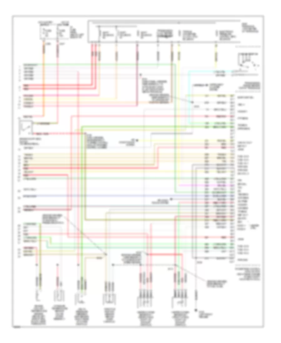
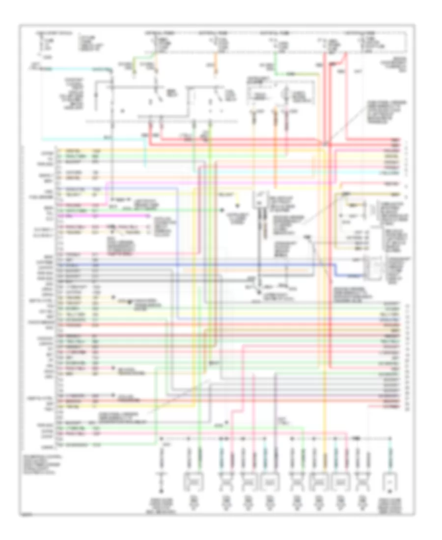
3.0L 12-Valve, Engine Performance Wiring Diagrams (1 of 3) for Ford Taurus G 1997

List of elements for 3.0L 12-Valve, Engine Performance Wiring Diagrams (1 of 3) for Ford Taurus G 1997:
- (dash panel harn, near breakout to constant control relay)
- (dash panel harness, near breakout to 42-pin black conn in left side of engine above transaxle)
- (engine harness, near breakout to heated oxygen sensor #21)
- (upper right center of cowl)
- Accs
- Air conditioning system (a/c high pressure switch)
- C225
- C250
- C251
- Check engine indicator
- Ckp feed
- Ckp rtn
- Constant control relay module (on left side of battery, behind headlamp)
- Cooling fans system (constant control relay module)
- Cooling fans system (hedf relay)
- Crankshaft position sensor (lower right side of eng)
- Data link connector (below
- Dlc
- Dlc bus (+)
- Dlc bus (-)
- Eam air pump (left front of vehicle, rear of bumper)
- Eam rly
- Eam solid state relay (left front of vehicle, rear of bumper)
- Ect
- Edf rly ctrl
- Eeec power fuse 30a
- Eeec relay
- Engine compartment fuse/relay box
- Evr
- Fpm
- Fuel gauge
- Fuel pump fuse 20a
- Fuel pump relay
- Fuse 20a
- G100 (left front fender)
- G104 (left front fender, near air cleaner)
- G123
- G123 (upper right center of cowl)
- Gnd
- Hedf rly ctrl
- Hego power fuse 10a
- Ho2s #12
- Horn fuse 15a
- Hot at all times
- Hot in start or run
- I/p fuse panel (below left side of i/p)
- Iat
- Ign coil a
- Ign coil b
- Ignition coil
- Instrument cluster
- Instrument cluster system (anti-slosh module)
- Kapwr
- Maf rtn
- Mil
- Nca
- Near breakout to heated oxygen sensor #11)
- Oct adj
- Octane adjust plug (right rear of eng compt, near pcm)
- Powertrain control module (pcm) (right rear corner of eng compt, mounted in cowl)
- Psp
- Pwr gnd
- Radio noise capacitor (on ignition coil)
- Red
- S105
- S108
- S112
- S120
- S133
- S135
- S137
- S144
- S148
- S149
- S155
- S156
- S158
- Ss #1
- Ss #2
- Ss #3
- Steering column)
- Tach
- Tacho- meter
- Tft
- Thermactor air bypass solenoid (above exhaust manifold, rear of eng)
- Thermactor pump fuse 30a
- To spark plugs
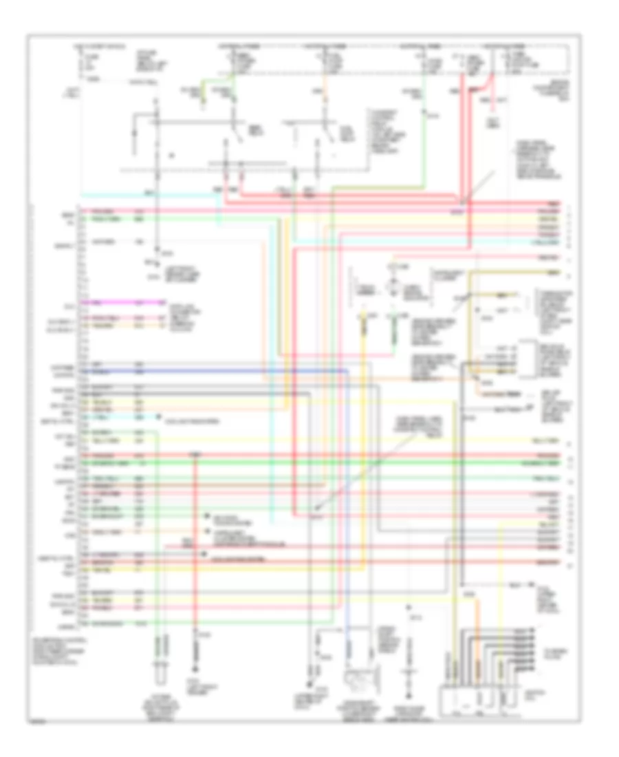
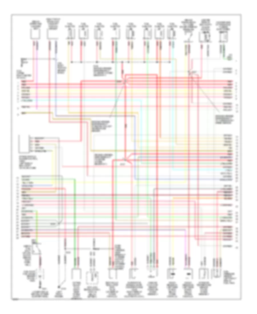
3.0L 12-Valve, Engine Performance Wiring Diagrams (2 of 3) for Ford Taurus G 1997
List of elements for 3.0L 12-Valve, Engine Performance Wiring Diagrams (2 of 3) for Ford Taurus G 1997:
- (behind transmission fill tube) power steering pressure switch
- (below spare tire) canister vent
- (center rear of eng compt) idle air control valve
- (dash panel harness, near breakout to 42-pin black conn in left side of engine above transaxle)
- (engine harness, near breakout to crankshaft position sensor)
- (engine harness, near breakout to engine oil pressure switch)
- (engine harness, near breakout to fuel inj #5)
- (left side of eng block) camshaft position sensor
- (lower middle section of rear quarter panel)
- (on rear side of transaxle) turbine shaft speed sensor
- Cam- shaft position sensor shield
- Egr vacuum regulator (evr) valve (on rear of intake manifold)
- Evaporative emission (evap) canister purge valve (right rear of eng compt, mounted on cowl)
- Fuel injector #1
- Fuel injector #2
- Fuel injector #3
- Fuel injector #4
- Fuel injector #5
- Fuel injector #6
- Fuel pressure sensor (left front side of fuel tank)
- Fuel pump/ fuel gauge sender (in fuel tank)
- G123 (upper right center of cowl)
- G401
- Inertia fuel shut- off (ifs) switch (behind right wheel well)
- Mass air flow (maf) sensor (near air intake assembly)
- Red
- S101
- S103
- S107
- S111
- S134
- Tan
- Vehicle speed sensor (vss) (rear center of eng compt, on transaxle)
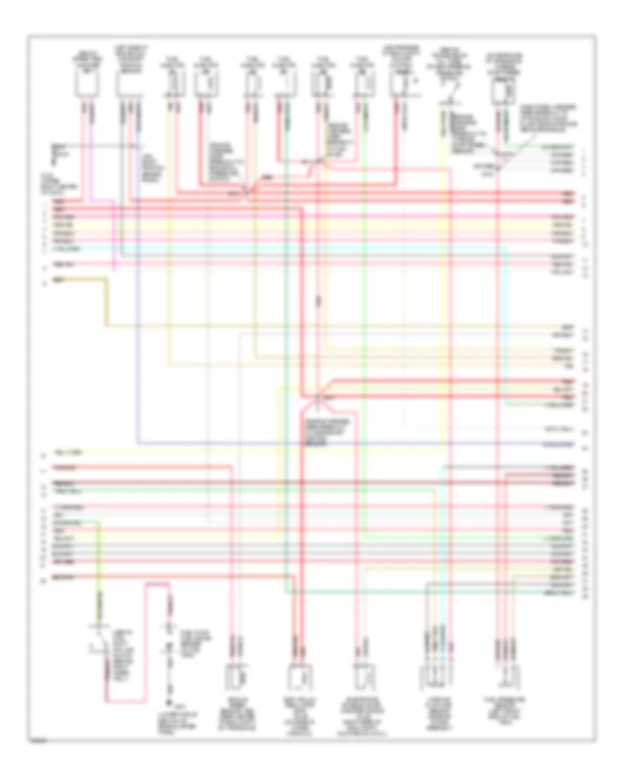
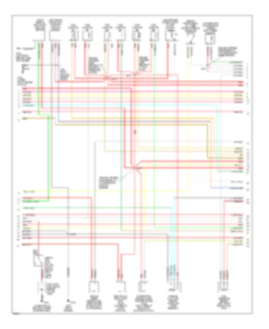
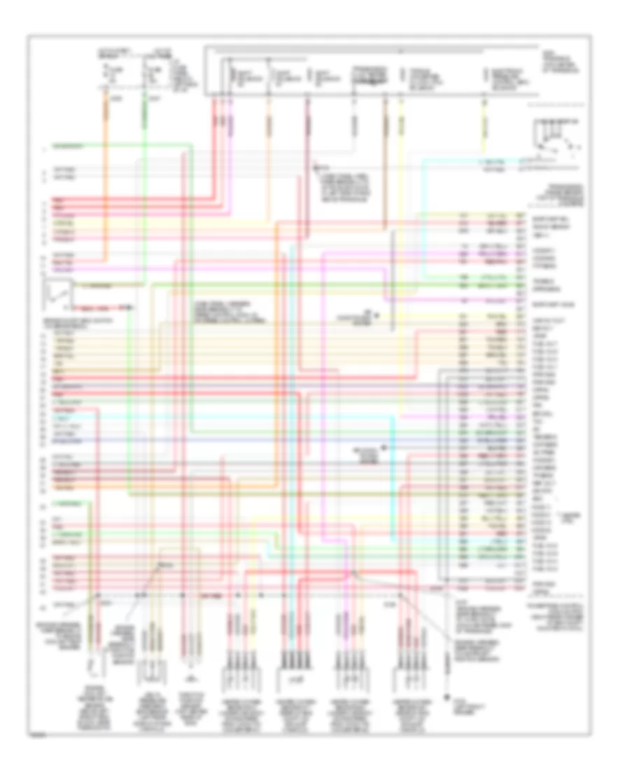
3.0L 12-Valve, Engine Performance Wiring Diagrams (3 of 3) for Ford Taurus G 1997
List of elements for 3.0L 12-Valve, Engine Performance Wiring Diagrams (3 of 3) for Ford Taurus G 1997:
- heated oxygen sensor #21 (lower left front of eng compt)
- (engine harness, near breakout to crankshaft position sensor)
- (engine harness, near breakout to engine oil pressure switch)
- (engine harness, near breakout to fuel inj #6)
- (engine harness, near breakout to turbine shaft speed sensor)
- (main harness, near breakout to speed control module or speed control jumper)
- A/c pres
- Air condi- tioning system
- Air conditioning system
- Ax4s transaxle (top center of transaxle)
- Boo
- Brake on/off (boo) switch (on brake pedal)
- C235
- C247
- Cmp sens
- Delta pressure feedback egr sensor (top left rear of eng)
- Dpfe sens
- Eam relay
- Electronic pressure control (epc) solenoid
- Engine coolant temperature sensor (above left side of eng block, near thermostat)
- Epc sol
- Evap canp sol
- Evap canp valve
- Fpm
- Ftp sens
- Fuel inj 1
- Fuel inj 2
- Fuel inj 3
- Fuel inj 4
- Fuel inj 5
- Fuel inj 6
- Fuse 15a
- Fuse 5a
- G100 (left front fender)
- Heated oxygen sensor #11 (back of eng)
- Heated oxygen sensor #12 (lower left side of eng)
- Heated oxygen sensor #22 (lower right side of eng)
- Heater ctrl
- Ho2s #11
- Ho2s #21
- Ho2s #22
- Ho2s 11
- Ho2s 12
- Ho2s 21
- Ho2s 22
- Hot at all times
- Hot in start
- I/p fuse panel (below left side of i/p)
- Iac
- Ign coil c
- Instrument cluster system
- Intake air temperature sensor (on air intake assembly)
- Maf sens
- Nca
- Or run
- Powertrain control module (pcm) (right rear corner of eng compt, mounted in cowl)
- Pwr gnd
- Red
- Red/pnk
- Ref volt
- S100
- S102
- S104
- S106
- S110
- S138
- Shift solenoid #1
- Shift solenoid #2
- Shift solenoid #3
- Sig rtn
- Tan
- Tcc
- Throttle position sensor (top center rear of eng)
- Torque converter clutch (tcc) solenoid
- Tp sens
- Tr sens
- Transmission fluid temper- ature sensor
- Transmission range sensor (top of transaxle)
- Tss sens
- Vpwr
- Vss (+)
- Wac rly out
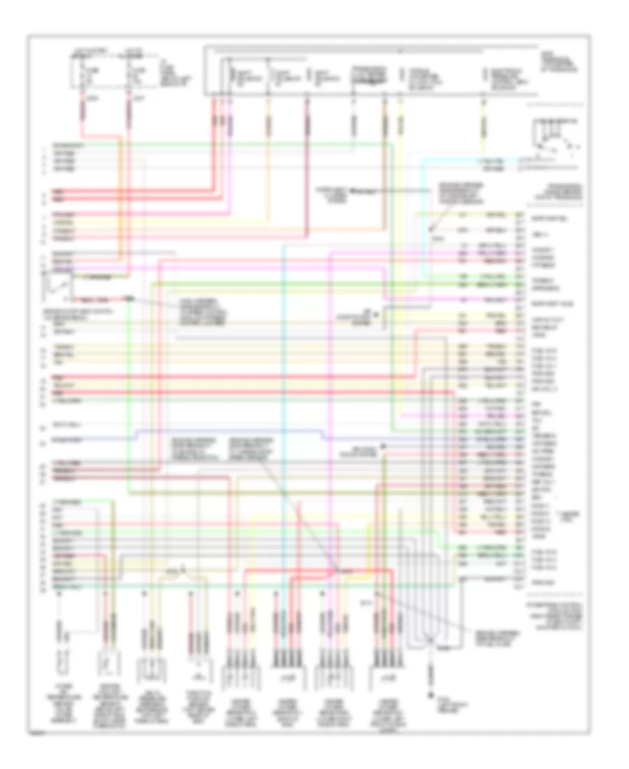
3.0L 24-Valve, Engine Performance Wiring Diagrams (1 of 3) for Ford Taurus G 1997
List of elements for 3.0L 24-Valve, Engine Performance Wiring Diagrams (1 of 3) for Ford Taurus G 1997:
- (dash panel harness, near breakout to 42-pin black conn in left side of engine above transaxle)
- (dash panel harness, near breakout to constant control relay)
- (left front fender, near g104 air cleaner)
- (upper right center of cowl)
- Accs
- Air condi- tioning system
- C225
- C250
- Check engine indicator
- Ckp feed
- Ckp rtn
- Constant control relay module (on left side of battery, behind headlamp)
- Cooling fans system
- Crank- shaft position sensor shield
- Crankshaft position sensor (lower right side of eng)
- Data link connector (below steering column)
- Dlc
- Dlc bus (+)
- Dlc bus (-)
- Ect
- Edf rly ctrl
- Eeec power fuse 30a
- Eeec relay
- Engine compartment fuse/relay box
- Evr
- Fpm
- Fuel pump fuse 20a
- Fuel pump relay
- Fuel sender
- Fuse 20a
- G100 (left front fender)
- G123
- Gnd
- Hedf rly ctrl
- Hego power fuse 15a
- Ho2s #12
- Horn fuse 10a
- Hot at all times
- Hot in start or run
- I/p fuse panel (below left side of i/p)
- Iat
- Ign coil a
- Ign coil b
- Ignition coil
- Imrc
- Instrument cluster
- Instrument cluster system
- Kapwr
- Maf rtn
- Mil
- Nca
- Oct adj
- Octane adjust plug (right rear of eng compt, near pcm)
- Powertrain control module (pcm) (right rear corner of eng compt, mounted in cowl)
- Psp
- Pwr gnd
- Radio noise capacitor (on ignition coil)
- Red
- S105
- S108
- S112
- S120
- S122
- S133
- S135
- S137
- S144
- S218 (main harness, near breakout to passive anti- theft system)
- S219
- Ss #1
- Ss #2
- Ss #3
- Tach
- Tacho- meter
- Tcs
- Tft
- To spark plugs
- Transmissions system
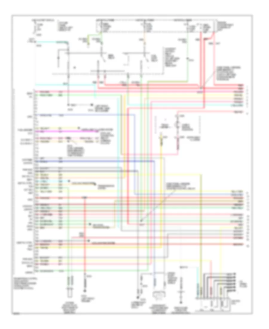
3.0L 24-Valve, Engine Performance Wiring Diagrams (2 of 3) for Ford Taurus G 1997
List of elements for 3.0L 24-Valve, Engine Performance Wiring Diagrams (2 of 3) for Ford Taurus G 1997:
- (behind transmission fill tube) power steering pressure switch
- (below spare tire) canister vent
- (center rear of eng compt) idle air control valve
- (engine harness, near breakout to engine coolant temperature sender)
- (engine harness, near breakout to heated oxygen sensor #11)
- (engine harness, near breakout to turbine shaft speed sensor)
- (left front fender)
- (lower middle section of rear quarter panel)
- (on rear side of transaxle) turbine shaft speed sensor
- (right top of eng block) camshaft position sensor
- Cam- shaft position sensor shield
- Egr vacuum regulator (evr) valve (on rear of intake manifold)
- Evaporative emission (evap) canister purge valve (right rear of eng compt, mounted on cowl)
- Fuel injector #1
- Fuel injector #2
- Fuel injector #3
- Fuel injector #4
- Fuel injector #5
- Fuel injector #6
- Fuel pressure sensor (left front side of fuel tank)
- Fuel pump/ fuel gauge sender (in fuel tank)
- G100
- G123 (upper right center of cowl)
- G401
- Inertia fuel shut- off (ifs) switch (behind right wheel well)
- Intake air temperature sensor (on air intake assembly)
- Intake manifold runner control (imrc) (left side of eng compt, on valve cover)
- Knock sensor (left upper rear of eng, below intake manifold)
- Mass air flow (maf) sensor (in eng air intake assembly)
- Red
- S106
- S107 (engine harness, near breakout to heated oxygen sensor #11)
- S147
- S150
- S152
- Tan
- Vehicle speed sensor (vss) (rear center of eng compt, on transaxle)
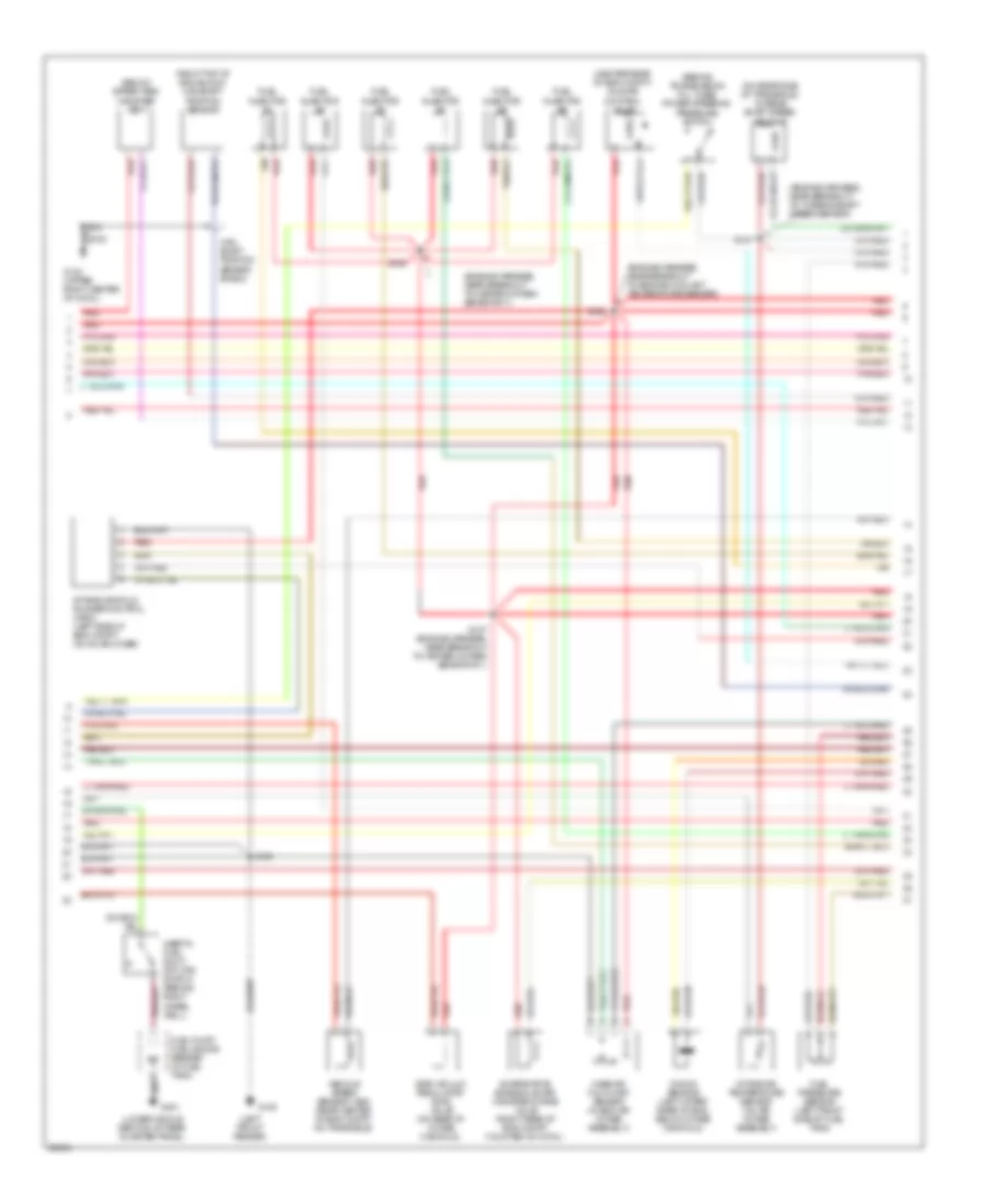
3.0L 24-Valve, Engine Performance Wiring Diagrams (3 of 3) for Ford Taurus G 1997
List of elements for 3.0L 24-Valve, Engine Performance Wiring Diagrams (3 of 3) for Ford Taurus G 1997:
- (dash panel harn, near breakout to 42-pin black conn in left side of eng above transaxle)
- (engine harness, near breakout to 10-pin white conn centered atop of transaxle)
- (engine harness, near breakout to campshaft position sensor)
- (engine harness, near breakout to crankshaft position sensor)
- (engine harness, near breakout to engine coolant temperature sender)
- (engine harness, near breakout to throttle position sensor)
- A/c pres
- Air condi- tioning system
- Air conditioning system
- Ax4n transaxle (top center of transaxle)
- Boo
- Brake on/off (boo) switch (on brake pedal)
- C235
- C247
- Cmp sens
- Delta pressure feedback egr sensor (top left rear of eng)
- Dpfe sens
- Electronic pressure control (epc) solenoid
- Engine coolant temperature sensor (above left side of eng block, near thermostat)
- Epc sol
- Evap canp sol
- Evap canp valve
- Fpm
- Ftp sens
- Fuel inj 1
- Fuel inj 2
- Fuel inj 3
- Fuel inj 4
- Fuel inj 5
- Fuel inj 6
- Fuse 15a
- Fuse 5a
- G100 (left front fender)
- Heated oxygen sensor #11 (rear of eng compt, on exhaust manifold)
- Heated oxygen sensor #12 (under car body downstream, from catalytic converter #1)
- Heated oxygen sensor #21 (rear of eng compt, on exhaust manifold)
- Heated oxygen sensor #22 (under car body downstream, from catalytic converter #2)
- Heater ctrl
- Ho2s #11
- Ho2s #21
- Ho2s #22
- Ho2s 11
- Ho2s 12
- Ho2s 21
- Ho2s 22
- Hot at all times i/p fuse panel (below left side of i/p)
- Hot in start
- Iac
- Ign coil c
- Instrument cluster system
- Knock sens
- Maf sens
- Nca
- Or run
- Powertrain control module (pcm) (right rear corner of eng compt, mounted in cowl)
- Pwr gnd
- Red
- Red/pnk
- Ref volt
- S102
- S104
- S106
- S134
- S138 (dash panel harness, near breakout to speed control module or speed control jumper)
- S151
- S153
- S157
- Shift solenoid #1
- Shift solenoid #2
- Shift solenoid #3
- Sig rtn
- Tan
- Tcc
- Tcil
- Throttle position sensor (top center rear of eng)
- Torque converter clutch (tcc) solenoid
- Tp sens
- Tr sens
- Transmission fluid temper- ature sensor
- Transmission range sensor (top of transaxle housing)
- Tss sens
- Vpwr
- Vss (+)
- Wac rly out
3.0L Flex Fuel, Engine Performance Wiring Diagrams (1 of 3) for Ford Taurus G 1997
List of elements for 3.0L Flex Fuel, Engine Performance Wiring Diagrams (1 of 3) for Ford Taurus G 1997:
- (dash panel harn, near breakout to constant control relay)
- (dash panel harness, near breakout to 42-pin black conn in left side of engine above transaxle)
- (engine harness, near breakout to heated oxygen sensor #11)
- (engine harness, near breakout to heated oxygen sensor #21)
- (left front fender, near g104 air cleaner)
- (not used)
- (upper right center of cowl)
- Accs
- Air condi- tioning system
- C225
- C250
- Check engine indicator
- Ckp feed
- Ckp rtn
- Constant control relay module (on left side of battery, behind headlamp)
- Cooling fans system
- Crank- shaft position sensor shield
- Crankshaft position sensor (lower right side of eng)
- Data link connector (below steering column)
- Dlc
- Dlc bus (+)
- Dlc bus (-)
- Dte
- Eam air pump (left front of vehicle, rear of bumper)
- Eam rly
- Eam solid state relay (left front of vehicle, rear of bumper)
- Ect
- Edf rly ctrl
- Eeec power fuse 30a
- Eeec relay
- Engine compartment fuse/relay box
- Evr
- Ff sens
- Fpm
- Fuel pump fuse 20a
- Fuel pump relay
- Fuse 20a
- G100 (left front fender)
- G123
- G123 (upper right center of cowl)
- Gnd
- Hedf rly ctrl
- Hego power fuse 15a
- Horn fuse 15a
- Hot at all times
- Hot in start or run
- I/p fuse panel (below left side of i/p)
- Iat
- Ign coil a
- Ign coil b
- Ignition coil
- Instrument cluster
- Instrument cluster system (distance to empty module)
- Kapwr
- Maf rtn
- Mil
- Nca
- Oct adj
- Octane adjust plug (right rear of eng compt, near pcm)
- Powertrain control module (pcm) (right rear corner of eng compt, mounted in cowl)
- Psp
- Pwr gnd
- Radio noise capacitor (near ignition coil)
- Red
- S105
- S108
- S112
- S120
- S133
- S135
- S137
- S144
- S148
- S149
- S155
- S156
- S158
- Ss #1
- Ss #2
- Ss #3
- Tach
- Tacho- meter
- Tft
- Ther- mactor pump fuse 30a
- Thermactor air bypass solenoid (left front of eng compt, near ignition coil)
- To spark plugs
3.0L Flex Fuel, Engine Performance Wiring Diagrams (2 of 3) for Ford Taurus G 1997
List of elements for 3.0L Flex Fuel, Engine Performance Wiring Diagrams (2 of 3) for Ford Taurus G 1997:
- (behind transmission fill tube) power steering pressure switch
- (center rear of eng compt) idle air control valve
- (engine harness, near breakout to crankshaft position sensor)
- (engine harness, near breakout to engine oil pressure switch)
- (engine harness, near breakout to fuel inj #5)
- (engine harness, near breakout to turbine shaft speed sensor)
- (left front fender)
- (left side of eng block) camshaft position sensor
- (lower middle section of rear quarter panel)
- (on rear side of transaxle) turbine shaft speed sensor
- (right rear of eng compt) flex fuel sensor)
- Cam- shaft position sensor shield
- Egr vacuum regulator (evr) valve (on rear of intake manifold)
- Evaporative emission (evap) canister purge valve (right rear of eng compt, mounted on cowl)
- Fuel injector #1
- Fuel injector #2
- Fuel injector #3
- Fuel injector #4
- Fuel injector #5
- Fuel injector #6
- Fuel pressure sensor (left front side of fuel tank)
- Fuel pump/ fuel gauge sender (in fuel tank)
- G100
- G104 (left front fender, near air cleaner)
- G123 (upper right center of cowl)
- G401
- Inertia fuel shut- off (ifs) switch (behind right wheel well)
- Mass air flow (maf) sensor (in eng air intake assembly)
- Red
- S101
- S103
- S106
- S107
- S108
- S111
- Tan
- Vehicle speed sensor (vss) (rear center of eng compt, on transaxle)
3.0L Flex Fuel, Engine Performance Wiring Diagrams (3 of 3) for Ford Taurus G 1997
List of elements for 3.0L Flex Fuel, Engine Performance Wiring Diagrams (3 of 3) for Ford Taurus G 1997:
- (engine harness, near breakout to crankshaft position sensor)
- (engine harness, near breakout to engine oil pressure switch)
- (engine harness, near breakout to fuel inj #6)
- A/c pres
- Air condi- tioning system
- Air conditioning system
- Ax4s transaxle (top center of transaxle)
- Boo
- Brake on/off (boo) switch (on brake pedal)
- C235
- C247
- Cmp sens
- Delta pressure feedback egr sensor (right rear of intake manifold)
- Dpfe sens
- Eam rly
- Electronic pressure control (epc) solenoid
- Engine coolant temperature sensor (above left side of eng block, near thermostat)
- Epc sol
- Evap canp sol
- Fpm
- Ftp sens
- Fuel inj 1
- Fuel inj 2
- Fuel inj 3
- Fuel inj 4
- Fuel inj 5
- Fuel inj 6
- Fuse 15a
- Fuse 5a
- G100 (left front fender)
- Heated oxygen sensor #11 (rear of eng compt, on exhaust manifold)
- Heated oxygen sensor #21 (front of eng compt, on exhaust manifold)
- Heater ctrl
- Ho2s #11
- Ho2s #21
- Ho2s 11
- Ho2s 21
- Hot at all times i/p fuse panel (below left side of i/p)
- Hot in start or run
- Iac
- Ign coil c
- Instrument cluster system
- Intake air temperature sensor (on air intake assembly)
- Maf sens
- Nca
- Powertrain control module (pcm) (right rear corner of eng compt, mounted in cowl)
- Pwr gnd
- Red
- Red/pnk
- Ref volt
- S100 (engine harness, near breakout to turbine shaft speed sensor)
- S102
- S104
- S106
- S110
- S134 (dash panel harness, near breakout to 42-pin black conn in left side of eng above transaxle)
- S138 (main harness, near breakout to speed control module or speed control jumper)
- Shift solenoid #1
- Shift solenoid #2
- Shift solenoid #3
- Sig rtn
- Tan
- Tcc
- Throttle position sensor (behind inake manifold)
- Torque converter clutch (tcc) solenoid
- Tp sens
- Tr sens
- Transmission fluid temper- ature sensor
- Transmission range sensor (top of transaxle)
- Tss sens
- Vpwr
- Vss (+)
- Wac rly out
3.4L
3.4L SHO, Engine Performance Wiring Diagrams (1 of 3) for Ford Taurus G 1997
List of elements for 3.4L SHO, Engine Performance Wiring Diagrams (1 of 3) for Ford Taurus G 1997:
- (dash panel harness, near breakout to 42-pin black conn in left side of engine above transaxle)
- (dash panel harness, near breakout to constant control relay)
- (engine harness, near breakout to evaporative emission canister valve)
- (engine harness, near breakout to heated oxygen sensor #21)
- (left front fender, near g104 air cleaner)
- (upper right center of cowl)
- Accs
- Air condi- tioning system
- C225
- C250
- Ccp #5
- Ccp #6
- Ccp #7
- Check engine indicator
- Ckp feed
- Ckp rtn
- Coil per plug #1
- Coil per plug #2
- Coil per plug #3
- Coil per plug #4
- Coil per plug #5
- Coil per plug #6
- Coil per plug #7
- Coil per plug #8
- Constant control relay module (on left side of battery, behind headlamp)
- Cooling fans system
- Cpp #1
- Cpp #3
- Crankshaft position sensor (lower right side of eng)
- Crankshaft position sensor shield
- Data link connector (below steering column)
- Dlc
- Dlc bus (+)
- Dlc bus (-)
- Eam air pump (left front vehicle, rear of bumper)
- Eam rly
- Eam solid state relay (left front of vehicle, rear of bumper)
- Ect
- Edf rly ctrl
- Eeec power fuse 30a
- Eeec relay
- Engine compartment fuse/relay box
- Evr
- Fpm
- Fuel pump fuse 20a
- Fuel pump relay
- Fuel sender
- Fuse 20a
- G123
- Gnd
- Hedf rly ctrl
- Hego power fuse 15a
- Ho2s #12
- Horn fuse 15a
- Hot at all times
- Hot in start or run
- I/p fuse panel (below left side of i/p)
- Iat
- Imrc
- Instrument cluster
- Instrument cluster system
- Kapwr
- Knock sens #2
- Maf rtn
- Mil
- Nca
- Oct adj
- Powertrain control module (pcm) (right rear corner of eng compt, mounted in cowl)
- Psp
- Pwr gnd
- Radio noise capacitor #1 (rear of eng, near cpp #4)
- Radio noise capacitor #2 (front of eng, above imrc)
- Red
- S108
- S137
- S144
- S148
- S149
- S156
- S161
- S162
- S163
- S218 (main harness, near breakout to passive anti- theft system)
- S219
- S447
- Ss #1
- Ss #2
- Ss #3
- Tach
- Tacho- meter
- Tcil
- Tcs
- Tft
- Ther- mactor pump fuse 30a
- Thermactor air bypass solenoid (above exhaust manifold, rear of eng)
- Transmissions system
3.4L SHO, Engine Performance Wiring Diagrams (2 of 3) for Ford Taurus G 1997
List of elements for 3.4L SHO, Engine Performance Wiring Diagrams (2 of 3) for Ford Taurus G 1997:
- (behind transmission fill tube) power steering pressure switch
- (below spare tire) canister vent
- (center rear of eng compt) idle air control valve
- (dash panel harness, near breakout to speed control module or speed control jumper)
- (engine harness, near breakout to engine coolant temperature sender)
- (engine harness, near breakout to heated oxygen sensor #11)
- (engine harness, near breakout to turbine shaft speed sensor)
- (left front fender)
- (lower middle section of rear quarter panel)
- (on rear side of transaxle) turbine shaft speed sensor
- (right top of eng block) camshaft position sensor
- Anti-lock brake control module (below battery)
- Cam- shaft position sensor shield
- Egr vacuum regulator (evr) valve (on rear of intake manifold)
- Evaporative emission (evap) canister purge valve (right rear of eng compt, mounted on cowl)
- Fuel injector #1
- Fuel injector #2
- Fuel injector #3
- Fuel injector #4
- Fuel injector #5
- Fuel injector #6
- Fuel injector #7
- Fuel injector #8
- Fuel pressure sensor (left front side of fuel tank)
- Fuel pump/ fuel gauge sender (in fuel tank)
- G100
- G123 (upper right center of cowl)
- G401
- Gnd
- Inertia fuel shut- off (ifs) switch (behind right wheel well)
- Intake air temperature sensor (on air intake assembly)
- Intake manifold runner control (imrc) (left side of eng compt, on valve cover)
- Knock sensor #1 (left rear of eng, below intake manifold)
- Knock sensor #2 (left rear of eng, below intake manifold)
- Mass air flow (maf) sensor (in eng air intake assembly)
- Octane adjust plug (right rear of eng compt, near pcm)
- Red
- S106
- S107
- S120
- S147
- S150
- S152 (engine harness, near breakout to heated oxygen sensor #11)
- Tan
- Tan/red
- Vss out
3.4L SHO, Engine Performance Wiring Diagrams (3 of 3) for Ford Taurus G 1997
List of elements for 3.4L SHO, Engine Performance Wiring Diagrams (3 of 3) for Ford Taurus G 1997:
- (dash panel harn, near breakout to 42-pin black conn in left side of eng above transaxle)
- (dash panel harness, near breakout to speed control module or speed control jumper)
- (engine harness, near breakout to campshaft position sensor)
- (engine harness, near breakout to engine coolant temp sender)
- (engine harness, near breakout to throttle position sensor)
- A/c pres
- Air condi- tioning system
- Air conditioning system
- Ax4n transaxle (top center of transaxle)
- Boo
- Brake on/off (boo) switch (on brake pedal)
- C235
- C247
- Cmp sens
- Cpp #2
- Cpp #4
- Cpp #8
- Delta pressure feedback egr sensor (left rear side of intake manifold)
- Dpfe sens
- Eam rly
- Electronic pressure control (epc) solenoid
- Engine coolant temperature sensor (above left side of eng block, near thermostat)
- Epc sol
- Evap canp sol
- Evap canp valve
- Fpm
- Ftp sens
- Fuel inj 1
- Fuel inj 2
- Fuel inj 3
- Fuel inj 4
- Fuel inj 5
- Fuel inj 6
- Fuel inj 7
- Fuel inj 8
- Fuse 15a
- Fuse 5a
- G100 (left front fender)
- Heated oxygen sensor #11 (rear of eng compt, on exhaust manifold)
- Heated oxygen sensor #12 (under car body, downstream from catalytic converter #1)
- Heated oxygen sensor #21 (rear of eng compt, on exhaust manifold)
- Heated oxygen sensor #22 (under car body, downstream from catalytic converter #2)
- Heater ctrl
- Ho2s #11
- Ho2s #21
- Ho2s #22
- Ho2s 11
- Ho2s 12
- Ho2s 21
- Ho2s 22
- Hot at all times i/p fuse panel (below left side of i/p)
- Hot in start or run
- Iac
- Knock sens #1
- Maf sens
- Nca
- Powertrain control module (pcm) (right rear corner of eng compt, mounted in cowl)
- Pwr gnd
- Red
- Red/pnk
- Ref volt
- S102
- S106
- S134
- S138
- S151
- S153
- S157 (engine harness, near breakout to 10-pin white conn centered atop of transaxle)
- Shift solenoid #1
- Shift solenoid #2
- Shift solenoid #3
- Sig rtn
- Tan
- Tan/red
- Tcc
- Throttle position sensor (top center rear of eng)
- Torque converter clutch (tcc) solenoid
- Tp sens
- Tr sens
- Transmission fluid temper- ature sensor
- Transmission range sensor (top of transaxle housing)
- Tss sens
- Vpwr
- Vss (+)
- Wac rly out