
ANTI-LOCK BRAKES
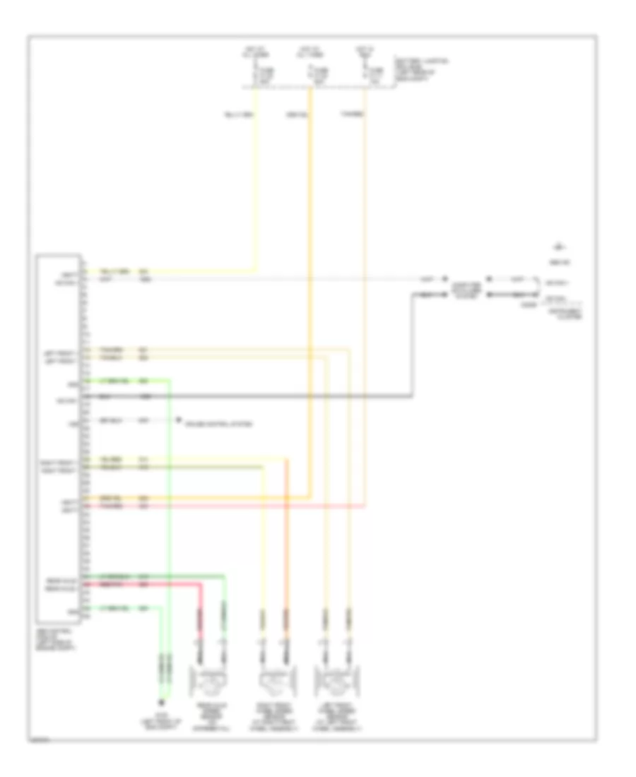
Anti-lock Brakes Wiring Diagram for Ford Cab & Chassis F350 Super Duty 2005
List of elements for Anti-lock Brakes Wiring Diagram for Ford Cab & Chassis F350 Super Duty 2005:
AIR CONDITIONINGCOOLING FANANTI-THEFTCRUISE CONTROLCOMPUTER DATA LINESANTI-LOCK BRAKESENGINE PERFORMANCEGROUND DISTRIBUTIONEXTERIOR LIGHTSHEADLIGHTSINSTRUMENT CLUSTERHORNNAVIGATIONINTERIOR LIGHTSPOWER DISTRIBUTIONPOWER SEATSPOWER WINDOWSPOWER DOOR LOCKSPOWER MIRRORSPOWER TOP/SUNROOFRADIOSTARTING/CHARGINGWARNING SYSTEMSTRANSMISSIONSUPPLEMENTAL RESTRAINTSSHIFT INTERLOCKWIPER/WASHER