SUPPLEMENTAL RESTRAINTS
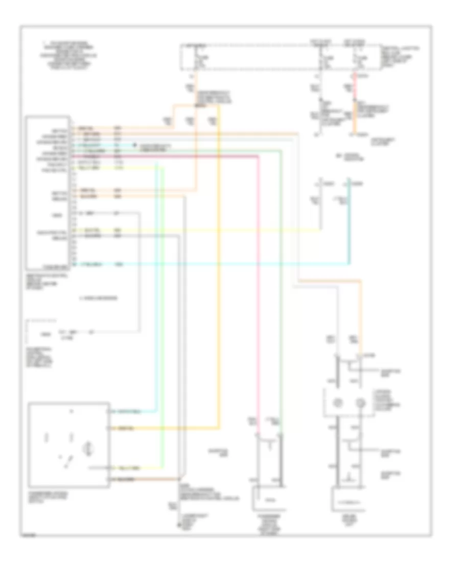
Supplemental Restraints Wiring Diagram for Ford Cab & Chassis F350 Super Duty 2005
List of elements for Supplemental Restraints Wiring Diagram for Ford Cab & Chassis F350 Super Duty 2005:
- (in steering column)
- (under right side of dash) g203
- Air bag feed
- Air bag indicator
- Air bag return
- Air bag sliding contact
- C175b
- C218b
- C220a
- C220b
- C220c
- C270a
- Central junction box (cjb) (behind lower left side of dash)
- Computer data lines system
- Driver air bag unit
- Fuse 10a
- Fuse 15a
- Gasoline engine
- Ground
- Hot in acc or run
- Hot in run
- Hot in run or start
- Ignition
- Indicator ctrl
- Instrument cluster
- Iso bus
- Nca
- Pad ind ctrl
- Pad input
- Passenger air bag deactivation (pad) switch
- Passenger air bag module (right side of dash)
- Pin shorting bars engaged when harness connector is disconnected from module: (shorting bars connected between pins 3-4, 6-7 & 20-21)
- Powertrain control module(pcm) (on left side of firewall)
- Restraints control module (behind center of dash)
- S299 (in main harness, near breakout for restraints control module)
- Shorting bar
- Tone driver
- Vems
 English