ANTI-LOCK BRAKES
All-Wheel ABS Wiring Diagram for Ford Cutaway E350 Super Duty 1999

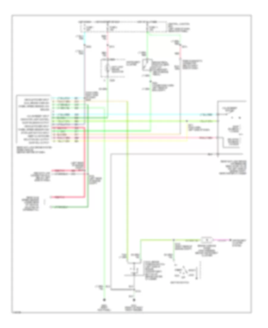
List of elements for All-Wheel ABS Wiring Diagram for Ford Cutaway E350 Super Duty 1999:
- (below left side of dash)
- (left front of engine compartment) low vacuum warning switch
- (left rear of engine compt) s117
- (left rear of engine compt) s124
- (not (not used) used)
- (not used)
- 4 wheel anti-lock brake system (4wabs) module (on left front frame rail)
- 4-wheel anti- lock brake system relay (behind center of dash)
- 87a
- Abs data link connector (dlc) (below left side of dash)
- Abs warning lamp output
- Accy
- Anti-lock brake indicator
- Battery junction box (in left front of engine compartment)
- Bpp switch input
- Brake pedal position (bpp) switch (on bracket, above brake pedal)
- Brake warn lamp high
- Brake warning indicator
- Brake warning lamp low
- C144
- C145
- C225
- C226
- Central junction box (left side of dash, near kick panel)
- Data link conn
- Data link connector (below left side of dash)
- Dual brake warning switch (left side of engine compartment, bottom of brake master cylinder)
- Electronic crash sensor (ecs) module (behind right side of dash)
- Fuse 1 20a
- Fuse 11 15a
- Fuse 19 60a
- Fuse 2 15a
- G100 (front of left front fender)
- G101 (front of right front fender)
- G202 (behind upper left side of dash)
- Ground
- Hot at all times
- Hot in run or start
- Ignition switch
- Instrument cluster
- Left front sensor high
- Left front sensor low
- Left front wheel speed sensor
- Lock
- Off
- Ohm
- Power
- Rear axle speed sensor
- Rear sensor high
- Rear sensor low
- Red/ pnk
- Red/pnk
- Relay ctrl output
- Right front sensor high
- Right front sensor low
- Right front wheel speed sensor
- Run
- S119 (left rear of engine compt)
- S122
- S125 (left side of engine compt)
- S132 (right rear of engine compt)
- S143
- S207
- S213
- S220 (top of steering column)
- S222
- S224 (lower dash harness, left rear of engine compt)
- S228
- S613
- Start
- Warning system
Rear Wheel ABS Wiring Diagram for Ford Cutaway E350 Super Duty 1999
List of elements for Rear Wheel ABS Wiring Diagram for Ford Cutaway E350 Super Duty 1999:
- (left rear of engine compt) s117
- (main harn, right side of dash) s200
- Abs data link connector (dlc) (below left side of dash)
- Accy
- Anti-lock brake indicator
- Brake pedal position (bpp) switch (on bracket, above brake pedal)
- Brake warning diode (main harness, behind instrument cluster)
- C225
- C226
- Central junction box (left side of dash, near kick panel)
- Dual brake warn sw
- Dual brake warning switch (left side of engine compartment, bottom of brake master cylinder)
- Dump sol output
- Dump solenoid 1-3 ohms
- Dump solenoid output
- Fuse 1 20a
- Fuse 11 15a
- Fuse 2 15a
- G101 (front of right front fender)
- G203 (right kick panel)
- Ground
- Hot at all times
- Hot in run
- Hot in start or run
- Ignition switch
- Indicator lamp control
- Instrument cluster
- Instrument cluster system
- Isolation sol output
- Isolation solenoid 3-6 ohms
- Keep alive power
- Lock
- Off
- Rabs diagnostic connector (below right side of dash)
- Rear anti-lock brake air pressure regulator valve (on left side of engine compt, near master cylinder)
- Rear anti-lock brake system (rabs) module (behind center of dash)
- Rear axle speed sensor (under rear of vehicle, mounted on differential)
- Red
- Red/pnk
- Run
- S124 (left rear of engine compt)
- S132 (right rear of engine compt)
- S143
- S211 (main harn, left side of dash)
- S213
- S214
- S222
- S224 (lower dash harn, left rear of eng compt)
- Start
- Stoplamp switch input
- Valve reset input
- Valve reset switch
- Vehicle power input
- Wheel speed sensor high
- Wheel speed sensor low