TRANSMISSION
5.4L
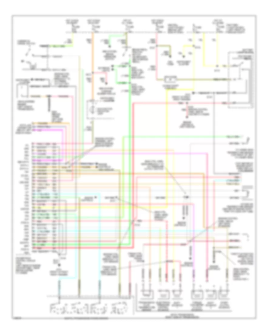
5.4L, A/T Wiring Diagram, 4R100 for Ford Cutaway E350 Super Duty 1999

List of elements for 5.4L, A/T Wiring Diagram, 4R100 for Ford Cutaway E350 Super Duty 1999:
- (eng control harn, near breakout to radio capacitor 1)
- (eng ctrl harn, near breakout to a/c pressure cutout switch)
- (eng ctrl harn, near breakout to pcm)
- (engine control harn, above left bank of engine)
- (engine control harness, left rear of engine compartment)
- (engine ctrl harn, near breakout to a/c press cut-out sw)
- (engine ctrl harn, near breakout to maf sensor)
- (in eng compt fuse box)
- (top center of engine compt) mass airflow (maf) sensor
- (trans ctrl harn, near breakout to dtr sensor)
- (trans ctrl harn, near trans) s102
- 4r100 transmission (right side of transmission)
- Abs system, brake pressure switch
- Abs system, warning buzzer module
- Battery junction box
- Battery junction box (left front of engine compt)
- Bpp
- Brake pedal position switch (on bracket, above brake pedal)
- Cc sol
- Central junction box (behind left side of dash)
- Cht
- Coast clutch solenoid
- Cylinder head temperature sensor (top front of left cylinder head)
- Data (+)
- Data (-)
- Data link connector (below left side of dash)
- Digital transmission range sensor
- Electronic pressure control solenoid
- Eng compt)
- Engine controls
- Engine controls (ngv module)
- Epc
- Exterior lights
- Fuse 10a
- Fuse 15a
- Fuse 30a
- Fuse 5a
- G101 (front of right front fender)
- G202 (behind upper left side of dash)
- Gen data
- Gnd
- Harn, above master cylinder)
- Hot at all times
- Hot in run or start
- Iat
- Instrument cluster
- Intake air temperature sensor (center of engine compt, part of clean air tube)
- Kapwr
- Maf
- Malfunction indicator lamp
- Mil
- Nca
- Ngv timer
- Od off
- Overdrive cancel switch
- Pcm diode
- Pcm power relay
- Powertrain control module (pcm) (left rear of engine compartment, near brake master cylinder)
- Pwr in
- Red
- S100
- S110
- S127
- S134 (eng ctrl harn, near breakout to pcm)
- S135
- S136
- S137
- S140
- S142
- S157
- S158
- S175
- S180 (engine control red
- S182
- S184
- S213
- S268
- Shift solenoid
- Sig rtn
- Ss1
- Ss2
- Tcc
- Tcil
- Tcs
- Tft
- Throttle position sensor (tps) (on top of engine, near air intake)
- Torque converter clutch solenoid
- Tps
- Tr1
- Tr2
- Tr3
- Tr4
- Transmission fluid temperature sensor
- Vehicle speed sensor (left side of transmission)
- Vref
- Vss
- Vss gnd
5.4L CNG
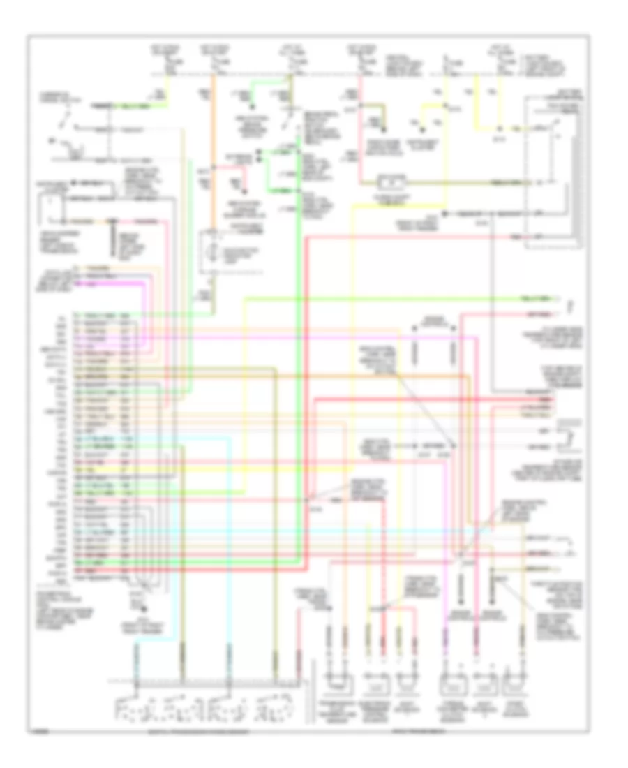
5.4L CNG, A/T Wiring Diagram, 4R100 for Ford Cutaway E350 Super Duty 1999
List of elements for 5.4L CNG, A/T Wiring Diagram, 4R100 for Ford Cutaway E350 Super Duty 1999:
- (eng control harn, near breakout to radio capacitor 1)
- (eng ctrl harn, near breakout to a/c pressure cutout switch)
- (eng ctrl harn, near breakout to pcm)
- (engine control harn, above left bank of engine)
- (engine control harness, left rear of engine compartment)
- (engine ctrl harn, near breakout to a/c press cut-out sw)
- (engine ctrl harn, near breakout to maf sensor)
- (in eng compt fuse box)
- (top center of engine compt) mass airflow (maf) sensor
- (trans ctrl harn, near breakout to dtr sensor)
- (trans ctrl harn, near trans) s102
- 4r100 transmission (right side of transmission)
- Abs system, brake pressure switch
- Abs system, warning buzzer module
- Battery junction box
- Battery junction box (left front of engine compt)
- Bpp
- Brake pedal position switch (on bracket, above brake pedal)
- Cc sol
- Central junction box (behind left side of dash)
- Cht
- Coast clutch solenoid
- Cylinder head temperature sensor (top front of left cylinder head)
- Data (+)
- Data (-)
- Data link connector (below left side of dash)
- Digital transmission range sensor
- Electronic pressure control solenoid
- Eng compt)
- Engine controls
- Engine controls (ngv module)
- Epc
- Exterior lights
- Fuse 10a
- Fuse 15a
- Fuse 30a
- Fuse 5a
- G101 (front of right front fender)
- G202 (behind upper left side of dash)
- Gen data
- Gnd
- Harn, above master cylinder)
- Hot at all times
- Hot in run or start
- Iat
- Instrument cluster
- Intake air temperature sensor (center of engine compt, part of clean air tube)
- Kapwr
- Maf
- Malfunction indicator lamp
- Mil
- Nca
- Ngv timer
- Od off
- Overdrive cancel switch
- Pcm diode
- Pcm power relay
- Powertrain control module (pcm) (left rear of engine compartment, near brake master cylinder)
- Pwr in
- Red
- S100
- S110
- S127
- S134 (eng ctrl harn, near breakout to pcm)
- S135
- S136
- S137
- S140
- S142
- S157
- S158
- S175
- S180 (engine control red
- S182
- S184
- S213
- S268
- Shift solenoid
- Sig rtn
- Ss1
- Ss2
- Tcc
- Tcil
- Tcs
- Tft
- Throttle position sensor (tps) (on top of engine, near air intake)
- Torque converter clutch solenoid
- Tps
- Tr1
- Tr2
- Tr3
- Tr4
- Transmission fluid temperature sensor
- Vehicle speed sensor (left side of transmission)
- Vref
- Vss
- Vss gnd
6.8L
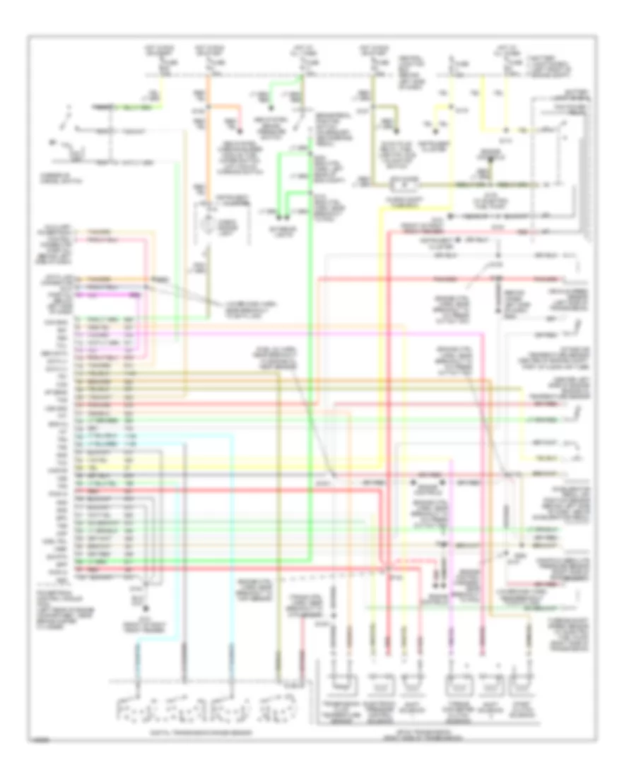
6.8L, A/T Wiring Diagram, 4R100 for Ford Cutaway E350 Super Duty 1999
List of elements for 6.8L, A/T Wiring Diagram, 4R100 for Ford Cutaway E350 Super Duty 1999:
- (behind upper left side of dash) g202
- (eng control harn, near breakout to a/c cutout switch)
- (eng control harn, near breakout to a/c pressure cutout switch)
- (eng ctrl harn, near breakout to pcm)
- (engine control harn, above left bank of engine)
- (engine ctrl harn, near breakout to a/c press cut-out sw)
- (engine ctrl harn, near breakout to maf sensor)
- (in eng compt fuse box)
- (top center of engine compt) mass airflow (maf) sensor
- (trans ctrl harn, near breakout to dtr sensor)
- (trans ctrl harn, near trans) s102
- 4r100 transmission
- Abs system, brake pressure switch
- Abs system, warning buzzer module
- Battery junction box
- Battery junction box (left front of engine compt)
- Bpp
- Brake pedal position switch (on bracket, above brake pedal)
- Cc sol
- Central junction box (behind left side of dash)
- Cht
- Coast clutch solenoid
- Cylinder head temperature sensor (top front of left cylinder head)
- Data (+)
- Data (-)
- Data link connector (below left side of dash)
- Digital transmission range sensor
- Electronic pressure control solenoid
- Eng compt)
- Engine controls
- Epc
- Exterior lights
- Fuse 10a
- Fuse 15a
- Fuse 30a
- Fuse 5a
- G101 (front of right front fender)
- Gen data
- Gnd
- Hot at all times
- Hot in run or start
- Iat
- Instrument cluster
- Intake air temperature sensor (center of engine compt, part of clean air tube)
- Kapwr
- Maf
- Malfunction indicator lamp
- Mil
- Nca
- Od off
- Overdrive cancel switch
- Pcm diode
- Pcm power relay
- Powertrain control module (pcm) (left rear of engine compartment, near brake master cylinder)
- Pwr in
- Radio noise capacitors, ignition coils
- Red
- S100
- S110
- S127
- S134 (eng ctrl harn, near breakout to pcm)
- S135
- S136
- S137
- S138
- S140
- S142
- S157
- S175
- S213
- S268
- Shift solenoid
- Sig rtn
- Ss1
- Ss2
- Tcc
- Tcil
- Tcs
- Tft
- Throttle position sensor (tps) (on top of engine, near air intake)
- Torque converter clutch solenoid
- Tps
- Tr1
- Tr2
- Tr3
- Tr4
- Transmission fluid temperature sensor
- Vehicle speed sensor (left side of transmission)
- Vref
- Vss
- Vss gnd
7.3L DI TURBO DIESEL
7.3L DI Turbo Diesel, A/T Wiring Diagram, 4R100 for Ford Cutaway E350 Super Duty 1999
List of elements for 7.3L DI Turbo Diesel, A/T Wiring Diagram, 4R100 for Ford Cutaway E350 Super Duty 1999:
- (behind upper left side of dash) g202
- (center left side of engine) engine oil temperature sensor
- (engine control harness, near breakout to pcm)
- (engine ctrl harn, near breakout to a/c press cut-out sw)
- (engine ctrl harn, near breakout to map sensor)
- (fuel inj harn, near breakout to engine oil temp sensor)
- (in eng compt fuse box)
- (lower dash harn, near breakout to data link)
- (trans ctrl harn, near breakout to dtr sensor)
- 4r100 transmission (right side of transmission)
- Abs system, brake pressure switch
- Abs system, warning buzzer module, fuel water switch, low vacuum warning switch
- Accelerator pedal (ap) position sensor (behind left side of dash, above accelerator pedal)
- Acel pdl
- Ap sens
- Auxiliary powertrain control connector (partial) (behind left side of dash)
- Battery junction box
- Battery junction box (left front of engine compt)
- Bpp
- Brake pedal position switch (on bracket, above brake pedal)
- Ccs
- Central junction box (behind left side of dash)
- Check engine light
- Chk eng
- Coast clutch solenoid
- Data (+)
- Data (-)
- Data link connector (dlc) (partial) (below left side of dash)
- Digital transmission range sensor
- Electronic pressure control solenoid
- Eng compt)
- Eng oil
- Engine controls
- Epc
- Exterior lights
- Fuse 10a
- Fuse 15a
- Fuse 30a
- Fuse 5a
- G101 (front of right front fender)
- Gen data
- Glow plug relay, fuel line htr, idle validation switch
- Gnd
- Hot at all times
- Hot in run or start
- Iat
- Instrument cluster
- Intake air temperature sensor (center of engine compt, part of clean air tube)
- Kapwr
- Manifold absolute pressure sensor (right side of engine compt)
- Map
- Nca
- Od off
- Overdrive cancel switch
- Pcm diode
- Pcm power relay
- Powertrain control module (pcm) (left rear of engine compartment, near brake master cylinder)
- Pwr in
- Red
- S1001
- S1007
- S110
- S127
- S134 (eng ctrl harn, near breakout to pcm)
- S135
- S136
- S137
- S138
- S139
- S140
- S142
- S146
- S175
- S176 (w/ electric fuel pump)
- S261
- S262
- S263
- Shift solenoid
- Sig rtn
- Ss1
- Ss2
- Tcc
- Tcil
- Tcs
- Tft
- Torque converter clutch solenoid
- Tr1
- Tr2
- Tr3
- Tr4
- Transmission fluid temperature sensor
- Tss
- Turbine shaft speed sensor (w/ electric fuel pump) (right side of transmission)
- Vehicle speed sensor (left side of transmission)
- Vref
- Vss
- Vss gnd