ANTI-LOCK BRAKES
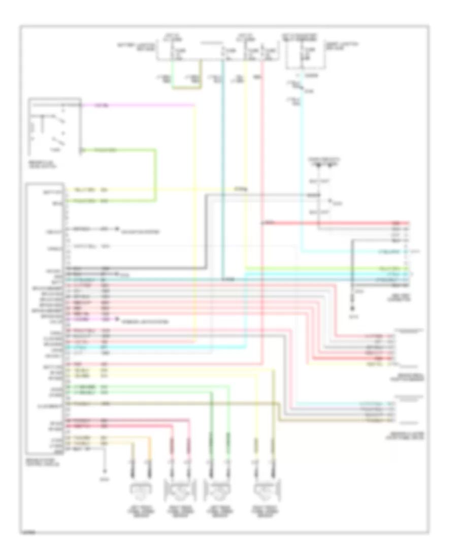
Anti-lock Brakes Wiring Diagram, Except Hybrid for Ford Escape 2006

List of elements for Anti-lock Brakes Wiring Diagram, Except Hybrid for Ford Escape 2006:
Anti-lock Brakes Wiring Diagram, Hybrid for Ford Escape 2006
List of elements for Anti-lock Brakes Wiring Diagram, Hybrid for Ford Escape 2006: