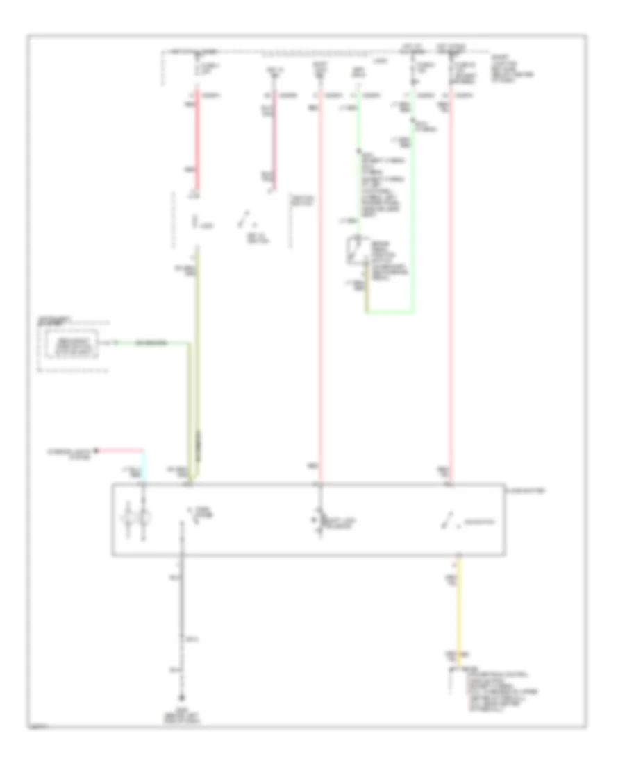
SHIFT INTERLOCK
Shift Interlock Wiring Diagram for Ford Escape 2006
List of elements for Shift Interlock Wiring Diagram for Ford Escape 2006:
- (except hybrid: at left kick panel)
- (hybrid: left rocker panel, near driver's seat)
- Bpp input
- Brake pedal position switch (on bracket, above brake pedal)
- C175b
- C2280a
- C2280c
- C2280e
- Floor shifter
- Fuse 32 10a (except hybrid)
- Fuse 4 10a
- Fuse 6 15a
- G206 (behind left side of dash)
- Hot at all times
- Hot in run or start
- Ignition switch
- Instrument cluster
- Interior lights system
- Key in ign
- Key in ignition
- Lock
- Logic
- O/d switch
- Park range
- Powertrain control module (pcm) (except hybrid) (3.0l: in recess on upper center of firewall) (2.3l: rear center of firewall)
- Red
- Redundant park switch status input
- S214
- S310 (hybrid)
- S314 (hybrid)
- S331 (except hybrid)
- Shift lock sol
- Shift lock solenoid
- Smart junction box (sjb) (below center of dash)
 English