ANTI-LOCK BRAKES
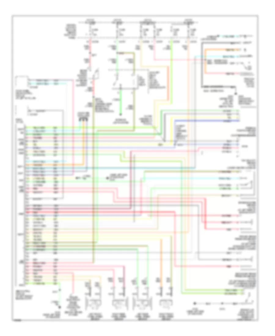
Anti-lock Brakes Wiring Diagram for Ford Expedition 2003
List of elements for Anti-lock Brakes Wiring Diagram for Ford Expedition 2003:
- (expedition)
- (expedition) (navigator)
- (in body main harness, near breakout to c214)
- (in main harness, in breakout to c210)
- (navigator)
- (near left side of radiator) g100
- - sig rtn
- Abs control module (at left side of engine compt)
- Auxiliary relay box 1 (w/ ivd) (at left front of engine compt)
- Brake booster sensor (w/ ivd) (at left rear of engine compt)
- Brake fluid level switch (in brake fluid reservoir, near firewall)
- Brake pedal position switch (on brake pedal support)
- C2188c
- C270b
- C270c
- C270d
- C270e
- C270f
- C3184b
- Central junction box (cjb) (behind right kick panel)
- Computer data lines system
- Exterior lights system
- Four-wheel drive control module (at left "b" pillar)
- Fuse 10a
- Fuse 20a
- Fuse 30a
- Fuse 5a
- Fuse 7.5a
- G100 (near left side of radiator)
- G200 (navigator) (behind right kick panel)
- G300 (expedition) on left "b" pillar, behind trim)
- Gnd
- Hot at all times
- Hot in start or run
- Illum
- Ind
- Interior lights system
- Iso
- Ivd stop lamp relay
- Left front wheel speed sensor
- Left rear wheel speed sensor
- Nca
- On/ off
- Primary brake pressure sensor (w/ ivd) (at left rear of engine compt, on brake master cylinder)
- Radio (w/ ivd)
- Red
- Red/ pnk
- Red/pnk
- Right front wheel speed sensor
- Right rear wheel speed sensor
- S101
- S104
- S123
- S2003 (in main harness, near breakout to brake pedal position switch)
- S202
- S205
- S277
- S281
- S373
- S387 s282
- Scp +
- Scp -
- Secondary brake pressure sensor (w/ ivd) (at left rear of engine compt, on brake master cylinder booster)
- Steering position sensor (w/ ivd) (on steering column)
- Tan/ red
- Tan/red
- Traction control switch (w/ ivd)
- Trailer electronic brake control connector (w/ ivd) (behind center of dash)
- Vbatt
- Vpwr
- Vref
- Yaw velocity sensor (w/ ivd) (under center console)
 English