STARTING/CHARGING
Charging Wiring Diagram for Ford Expedition 2003

List of elements for Charging Wiring Diagram for Ford Expedition 2003:
- (in engine control sensor harness, near breakout to thermostatic expansion valve switch assembly)
- (on right side of firewall) powertrain control module (pcm)
- Battery
- C102a
- C175b
- C220a
- C270a
- Central junction box (cjb) (behind right kick panel)
- Charge indicator
- Fuse 10a
- G103 (on right side of engine compartment, on fender)
- G104 (on right side of engine compartment, on frame rail)
- G105 (on right side of engine)
- Generator
- Instrument cluster
- Red
- S1001
- S1002
- S110
- S111
- Starter motor
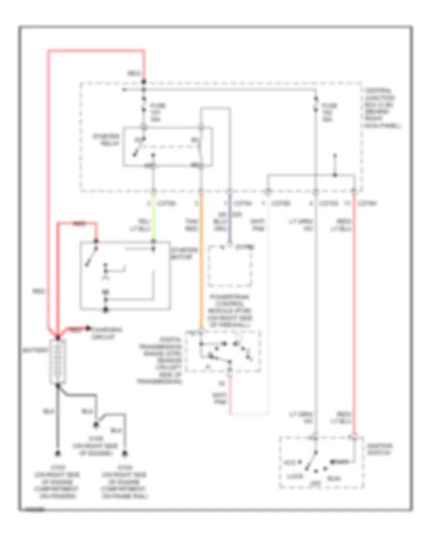
Starting Wiring Diagram for Ford Expedition 2003
List of elements for Starting Wiring Diagram for Ford Expedition 2003:
- Acc
- Battery
- C175b
- C270a
- C270d
- C270g
- C270h
- Central junction box (cjb) (behind right kick panel)
- Charging circuit
- Digital transmission range (dtr) sensor (on left side of transmission)
- Fuse 30a
- G103 (on right side of engine compartment, on fender)
- G104 (on right side of engine compartment, on frame rail)
- G105 (on right side of engine)
- Ignition switch
- Lock
- Off
- Powertrain control module (pcm) (on right side of firewall)
- Red
- Run
- Start
- Starter motor
- Starter relay
- Tan/ red