ANTI-LOCK BRAKES
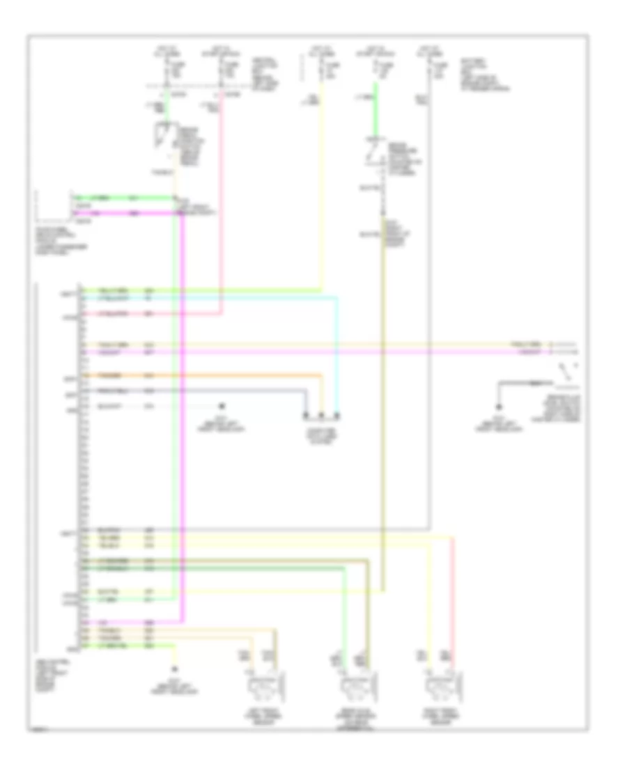
Anti-lock Brake Wiring Diagrams, Early Production for Ford Explorer 2002

List of elements for Anti-lock Brake Wiring Diagrams, Early Production for Ford Explorer 2002:
Anti-lock Brake Wiring Diagrams, Late Production with Traction Control for Ford Explorer 2002
List of elements for Anti-lock Brake Wiring Diagrams, Late Production with Traction Control for Ford Explorer 2002:
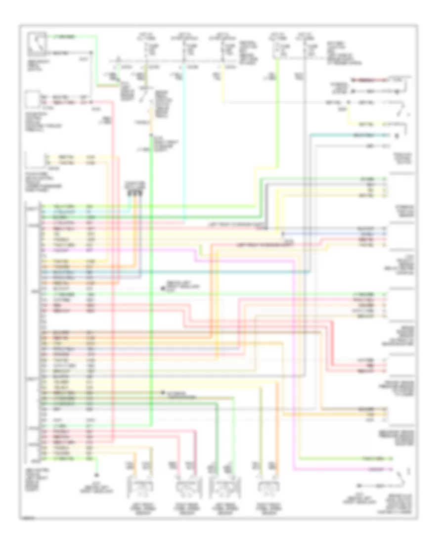
Anti-lock Brake Wiring Diagrams, Late Production without Traction Control for Ford Explorer 2002
List of elements for Anti-lock Brake Wiring Diagrams, Late Production without Traction Control for Ford Explorer 2002: