TRANSMISSION
4.0L
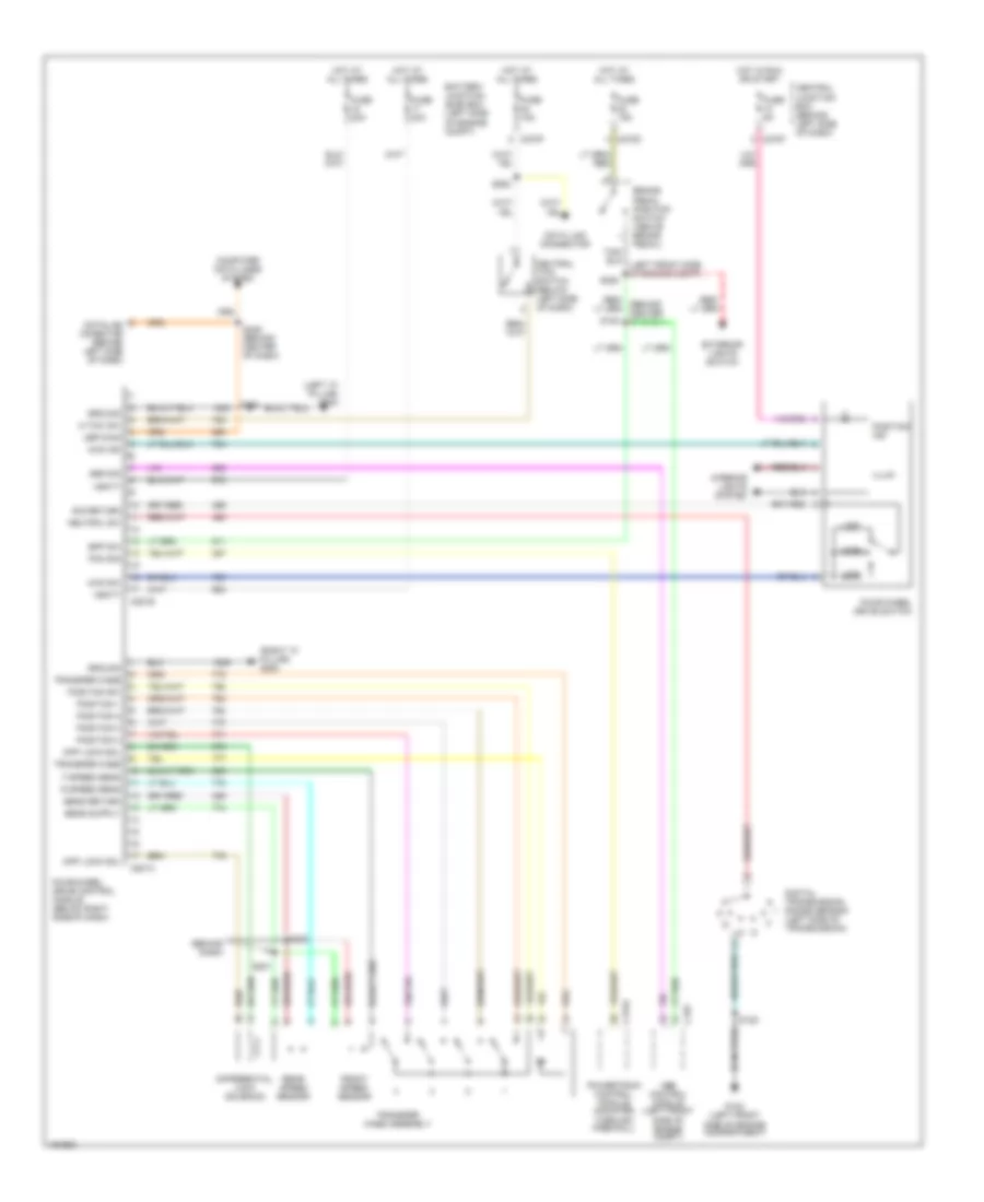
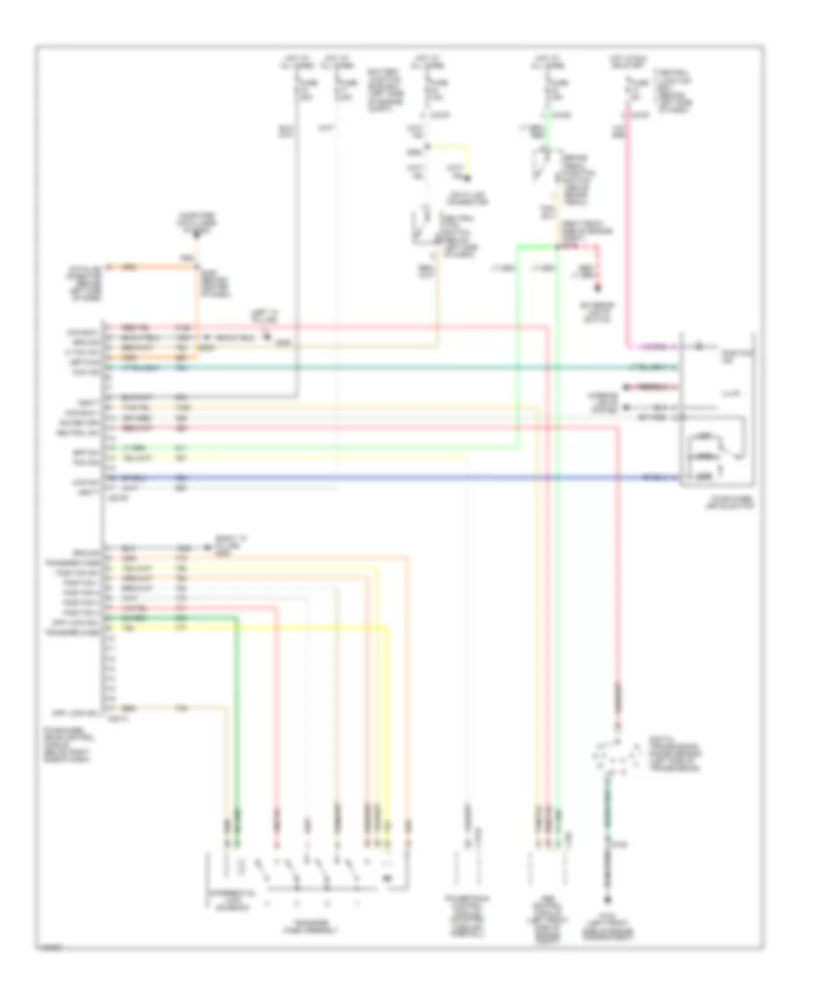
4.0L, A/T Wiring Diagram, Early Production for Ford Explorer 2002

List of elements for 4.0L, A/T Wiring Diagram, Early Production for Ford Explorer 2002:
- (4.0l)
- (4.6l)
- (behind center of dash)
- (behind left side of dash) data link connector
- (left front side of engine compt)
- (left side of engine compt)
- (mounted through firewall) powertrain control module
- (right rear side of engine compt)
- (right side of engine compt) s102
- (vehicle underbody) s101
- 4wd
- 4wd circuit
- Anti-lock brakes system
- Battery junction (bjb) box (left side of engine compt)
- Brake in
- Brake pedal position switch (above brake pedal)
- C175a
- C175b
- C175c
- C220a
- C220b
- C270d
- C270f
- Central junction box (behind left side of dash)
- Cht
- Cylinder head temperature sensor (4.6l) (top front of cylinder head)
- Digital transmission range sensor (left side of transmission)
- Dlc
- Ect
- Engine controls system
- Engine coolant temperature sensor (4.0l) (top right of engine)
- Exterior lights switch
- Fuse 15a
- Fuse 40a
- Fuse 5a
- G101
- G104
- G105
- Ground
- Heated o2 sensors, vapor management valve, evr solenoid valve
- Hot at all times
- Hot in run or start
- Instrument cluster
- Intermediate shaft speed sensor (left side of transmission)
- Iss
- Joint connector (part of battery junction box)
- O/d off
- Oss
- Output shaft speed sensor (left rear of transmission)
- Pcm power diode
- Pcm power relay
- Pcs a
- Pcs b
- Pcs c
- Power
- Pressure control solenoids
- Red
- Return
- S105
- S116
- S120
- S129 (at right front fender)
- S130 (right rear of engine compt)
- S132
- S210
- S211
- S220
- Scp+
- Scp-
- Shift solenoids
- Sig rtn
- Ss a
- Ss b
- Ss c
- Ss d
- Tcc sol
- Tcs
- Tft
- Throttle postion sensor (top of throttle body)
- Torque conv clutch solenoid
- Tps
- Tr1
- Tr2
- Tr3a
- Tr4
- Trans- mission control switch (end of shift lever)
- Transmission fluid temperature sensor
- Transmission solenoid body assembly
- Tss
- Turbine shaft speed sensor (left side of transmission)
- V ref
- Vbatt
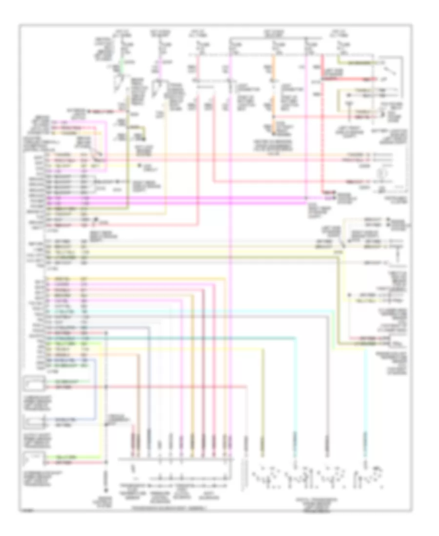
4.0L, A/T Wiring Diagram, Late Production for Ford Explorer 2002
List of elements for 4.0L, A/T Wiring Diagram, Late Production for Ford Explorer 2002:
- (4.0l)
- (4.6l)
- (at right front fender)
- (behind center of dash)
- (behind left side of dash) data link connector
- (left front side of engine compt)
- (left side of engine compt)
- (mounted through firewall) powertrain control module
- (right rear side of engine compt)
- (right side of engine compt) s102
- (vehicle underbody) s101
- 4wd
- 4wd circuit
- Battery junction (bjb) box (left side of engine compt)
- Brake in
- Brake pedal position switch (above brake pedal)
- C175a
- C175b
- C175c
- C220a
- C220b
- C270d
- C270f
- Central junction box (behind left side of dash)
- Cht
- Cylinder head temperature sensor (4.6l) (top front of cylinder head)
- Digital transmission range sensor (left side of transmission)
- Dlc
- Ect
- Engine controls system
- Engine coolant temperature sensor (4.0l) (top right of engine)
- Exterior lights switch
- Fuse 15a
- Fuse 40a
- Fuse 5a
- G101
- G104
- G105
- Ground
- Heated o2 sensors, vapor management valve, evr solenoid valve
- Hot at all times
- Hot in run or start
- Instrument cluster
- Intermediate shaft speed sensor (left side of transmission)
- Iss
- Joint connector (part of battery junction box)
- O/d off
- Oss
- Output shaft speed sensor (left rear of transmission)
- Pcm power diode
- Pcm power relay
- Pcs a
- Pcs b
- Pcs c
- Power
- Pressure control solenoids
- Red
- Return
- S105
- S116
- S120
- S129
- S130 (right rear of engine compt)
- S132
- S210
- S211
- Scp+
- Scp-
- Shift solenoids
- Sig rtn
- Ss a
- Ss b
- Ss c
- Ss d
- Tcc sol
- Tcs
- Tft
- Throttle postion sensor (top of throttle body)
- Torque conv clutch solenoid
- Tps
- Tr1
- Tr2
- Tr3a
- Tr4
- Trans- mission control switch (end of shift lever)
- Transmission fluid temperature sensor
- Transmission solenoid body assembly
- Tss
- Turbine shaft speed sensor (left side of transmission)
- V ref
- Vbatt
4WD Wiring Diagram, Early Production for Ford Explorer 2002
List of elements for 4WD Wiring Diagram, Early Production for Ford Explorer 2002:
- (behind center of dash)
- (behind dash)
- (behind right side of dash) s237
- (left "a" pillar)
- (left front side of engine compartment)
- (right "a" pillar)
- 4wd hi
- 4wd high ind
- 4wd ind
- 4wd lo
- 4wd sw
- Abs comm
- Abs control module (left front side of engine compt)
- Abs/pcm comm
- Battery junction (bjb) box (left side of engine compt)
- Bpp sw
- Brake pedal position switch (above brake pedal)
- C155
- C175a
- C201b
- C220a
- C220b
- C270d
- C270e
- C270f
- C270h
- C281a
- C281b
- Central junction box (behind left side of dash)
- Computer data lines system
- Data link conector
- Datalink conector (behind left side of dash)
- Diff lock sol
- Differential lock solenoid
- Digital transmission range sensor (left side of transmission)
- Door ajar
- Exterior lights switch
- F speed sens
- Four-wheel drive control module (below right side of dash)
- Four-wheel drive switch
- Front speed sensor
- Fuse 15a
- Fuse 20a
- Fuse 5a
- G102 (left front side of engine compartment)
- G202
- G300
- Generic electronic module (behind right side of dash)
- Ground
- High
- Hot at all times
- Hot in run or acc
- Hot in run or start
- Hot in start
- Illum
- Instrument cluster
- Interior lights system
- Iso bus
- Joint connector (part of battery junction box)
- Low
- N tow sw
- Neutral sw
- Neutral tow switch (below left side of dash)
- Off
- Pcm comm
- Position 1
- Position 2
- Position 3
- Position 4
- Position ind
- Position sw
- Powertrain control module (mounted through firewall)
- R speed sens
- Rear speed sensor
- S119 (left front side of engine compt)
- S125
- S200
- S201
- S210
- S211
- S220
- S228 (behind center of dash)
- S230
- S235
- S236
- S245
- Sens return
- Transfer case
- Transfer case assembly
- Vbatt
- Vpwr
4WD Wiring Diagram, Late Production with Traction Control for Ford Explorer 2002
List of elements for 4WD Wiring Diagram, Late Production with Traction Control for Ford Explorer 2002:
- (left "a" pillar)
- (rght front side of engine compt) s179
- (right "a" pillar) g200
- 4wd ind
- 4wd sw
- Abs control module (left front side of engine compt)
- Battery junction (bjb) box (left side of engine compt)
- Bpp sw
- Brake pedal position switch (above brake pedal)
- C155
- C175a
- C270d
- C270f
- C281a
- C281b
- Can bus +
- Can bus -
- Central junction box (behind left side of dash)
- Computer data lines system
- Data link connector
- Datalink conector (behind left side of dash)
- Diff lock sol
- Differential lock solenoid
- Digital transmission range sensor (left side of transmission)
- Exterior lights switch
- Four-wheel drive control module (below right side of dash)
- Four-wheel drive switch
- Fuse 15a
- Fuse 20a
- Fuse 5a
- G102 (left front side of engine compartment)
- G300
- Ground
- High
- Hot at all times
- Hot in run or start
- Illum
- Interior lights system
- Low
- N tow sw
- Neutral sw
- Neutral tow switch (below left side of dash)
- Off
- Pcm sig
- Position 1
- Position 2
- Position 3
- Position 4
- Position ind
- Position sw
- Powertrain control module (mounted through firewall)
- S125
- S230
- S246 (behind center of dash)
- S263
- Sig return
- Transfer case
- Transfer case assembly
- Ubp diag
- Vbatt
4WD Wiring Diagram, Late Production without Traction Control for Ford Explorer 2002
List of elements for 4WD Wiring Diagram, Late Production without Traction Control for Ford Explorer 2002:
- (behind dash)
- (left "a" pillar) g300
- (right "a" pillar) g200
- 4wd ind
- 4wd sw
- Abs control module (left front side of engine compt)
- Abs sig
- Battery junction (bjb) box (left side of engine compt)
- Bpp sw
- Brake pedal position switch (above brake pedal)
- C155
- C175a
- C270d
- C270f
- C281a
- C281b
- Central junction box (behind left side of dash)
- Computer data lines system
- Data link connector
- Datalink conector (behind left side of dash)
- Diff lock sol
- Differential lock solenoid
- Digital transmission range sensor (left side of transmission)
- Exterior lights switch
- F speed sens
- Four-wheel drive control module (below right side of dash)
- Four-wheel drive switch
- Front speed sensor
- Fuse 15a
- Fuse 20a
- Fuse 5a
- G102 (left front side of engine compartment)
- Ground
- High
- Hot at all times
- Hot in run or start
- Illum
- Interior lights system
- Low
- N tow sw
- Neutral sw
- Neutral tow switch (below left side of dash)
- Off
- Pcm sig
- Position 1
- Position 2
- Position 3
- Position 4
- Position ind
- Position sw
- Powertrain control module (mounted through firewall)
- R speed sens
- Rear speed sensor
- S120
- S125
- S200
- S201
- S220
- S230
- S246 (behind center of dash)
- S263
- Sens return
- Sig return
- Transfer case
- Transfer case assembly
- Ubp diag
- Vbatt
4.6L
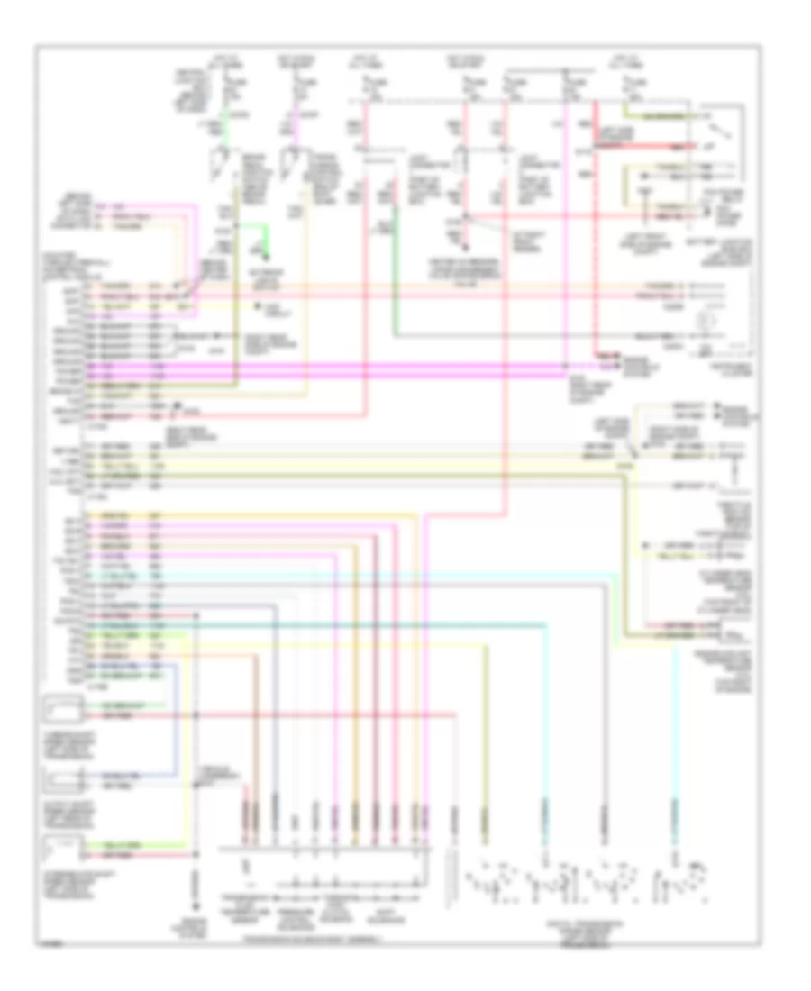
4.6L, A/T Wiring Diagram, Early Production for Ford Explorer 2002
List of elements for 4.6L, A/T Wiring Diagram, Early Production for Ford Explorer 2002:
- (4.0l)
- (4.6l)
- (behind center of dash)
- (behind left side of dash) data link connector
- (left front side of engine compt)
- (left side of engine compt)
- (mounted through firewall) powertrain control module
- (right rear side of engine compt)
- (right side of engine compt) s102
- (vehicle underbody) s101
- 4wd
- 4wd circuit
- Anti-lock brakes system
- Battery junction (bjb) box (left side of engine compt)
- Brake in
- Brake pedal position switch (above brake pedal)
- C175a
- C175b
- C175c
- C220a
- C220b
- C270d
- C270f
- Central junction box (behind left side of dash)
- Cht
- Cylinder head temperature sensor (4.6l) (top front of cylinder head)
- Digital transmission range sensor (left side of transmission)
- Dlc
- Ect
- Engine controls system
- Engine coolant temperature sensor (4.0l) (top right of engine)
- Exterior lights switch
- Fuse 15a
- Fuse 40a
- Fuse 5a
- G101
- G104
- G105
- Ground
- Heated o2 sensors, vapor management valve, evr solenoid valve
- Hot at all times
- Hot in run or start
- Instrument cluster
- Intermediate shaft speed sensor (left side of transmission)
- Iss
- Joint connector (part of battery junction box)
- O/d off
- Oss
- Output shaft speed sensor (left rear of transmission)
- Pcm power diode
- Pcm power relay
- Pcs a
- Pcs b
- Pcs c
- Power
- Pressure control solenoids
- Red
- Return
- S105
- S116
- S120
- S129 (at right front fender)
- S130 (right rear of engine compt)
- S132
- S210
- S211
- S220
- Scp+
- Scp-
- Shift solenoids
- Sig rtn
- Ss a
- Ss b
- Ss c
- Ss d
- Tcc sol
- Tcs
- Tft
- Throttle postion sensor (top of throttle body)
- Torque conv clutch solenoid
- Tps
- Tr1
- Tr2
- Tr3a
- Tr4
- Trans- mission control switch (end of shift lever)
- Transmission fluid temperature sensor
- Transmission solenoid body assembly
- Tss
- Turbine shaft speed sensor (left side of transmission)
- V ref
- Vbatt
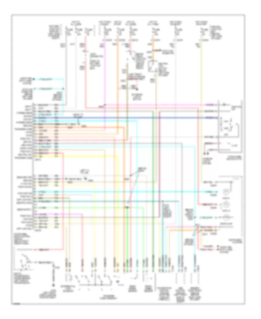
4.6L, A/T Wiring Diagram, Late Production for Ford Explorer 2002
List of elements for 4.6L, A/T Wiring Diagram, Late Production for Ford Explorer 2002:
- (4.0l)
- (4.6l)
- (at right front fender)
- (behind center of dash)
- (behind left side of dash) data link connector
- (left front side of engine compt)
- (left side of engine compt)
- (mounted through firewall) powertrain control module
- (right rear side of engine compt)
- (right side of engine compt) s102
- (vehicle underbody) s101
- 4wd
- 4wd circuit
- Battery junction (bjb) box (left side of engine compt)
- Brake in
- Brake pedal position switch (above brake pedal)
- C175a
- C175b
- C175c
- C220a
- C220b
- C270d
- C270f
- Central junction box (behind left side of dash)
- Cht
- Cylinder head temperature sensor (4.6l) (top front of cylinder head)
- Digital transmission range sensor (left side of transmission)
- Dlc
- Ect
- Engine controls system
- Engine coolant temperature sensor (4.0l) (top right of engine)
- Exterior lights switch
- Fuse 15a
- Fuse 40a
- Fuse 5a
- G101
- G104
- G105
- Ground
- Heated o2 sensors, vapor management valve, evr solenoid valve
- Hot at all times
- Hot in run or start
- Instrument cluster
- Intermediate shaft speed sensor (left side of transmission)
- Iss
- Joint connector (part of battery junction box)
- O/d off
- Oss
- Output shaft speed sensor (left rear of transmission)
- Pcm power diode
- Pcm power relay
- Pcs a
- Pcs b
- Pcs c
- Power
- Pressure control solenoids
- Red
- Return
- S105
- S116
- S120
- S129
- S130 (right rear of engine compt)
- S132
- S210
- S211
- Scp+
- Scp-
- Shift solenoids
- Sig rtn
- Ss a
- Ss b
- Ss c
- Ss d
- Tcc sol
- Tcs
- Tft
- Throttle postion sensor (top of throttle body)
- Torque conv clutch solenoid
- Tps
- Tr1
- Tr2
- Tr3a
- Tr4
- Trans- mission control switch (end of shift lever)
- Transmission fluid temperature sensor
- Transmission solenoid body assembly
- Tss
- Turbine shaft speed sensor (left side of transmission)
- V ref
- Vbatt
4WD Wiring Diagram, Early Production for Ford Explorer 2002
List of elements for 4WD Wiring Diagram, Early Production for Ford Explorer 2002:
- (behind center of dash)
- (behind dash)
- (behind right side of dash) s237
- (left "a" pillar)
- (left front side of engine compartment)
- (right "a" pillar)
- 4wd hi
- 4wd high ind
- 4wd ind
- 4wd lo
- 4wd sw
- Abs comm
- Abs control module (left front side of engine compt)
- Abs/pcm comm
- Battery junction (bjb) box (left side of engine compt)
- Bpp sw
- Brake pedal position switch (above brake pedal)
- C155
- C175a
- C201b
- C220a
- C220b
- C270d
- C270e
- C270f
- C270h
- C281a
- C281b
- Central junction box (behind left side of dash)
- Computer data lines system
- Data link conector
- Datalink conector (behind left side of dash)
- Diff lock sol
- Differential lock solenoid
- Digital transmission range sensor (left side of transmission)
- Door ajar
- Exterior lights switch
- F speed sens
- Four-wheel drive control module (below right side of dash)
- Four-wheel drive switch
- Front speed sensor
- Fuse 15a
- Fuse 20a
- Fuse 5a
- G102 (left front side of engine compartment)
- G202
- G300
- Generic electronic module (behind right side of dash)
- Ground
- High
- Hot at all times
- Hot in run or acc
- Hot in run or start
- Hot in start
- Illum
- Instrument cluster
- Interior lights system
- Iso bus
- Joint connector (part of battery junction box)
- Low
- N tow sw
- Neutral sw
- Neutral tow switch (below left side of dash)
- Off
- Pcm comm
- Position 1
- Position 2
- Position 3
- Position 4
- Position ind
- Position sw
- Powertrain control module (mounted through firewall)
- R speed sens
- Rear speed sensor
- S119 (left front side of engine compt)
- S125
- S200
- S201
- S210
- S211
- S220
- S228 (behind center of dash)
- S230
- S235
- S236
- S245
- Sens return
- Transfer case
- Transfer case assembly
- Vbatt
- Vpwr
4WD Wiring Diagram, Late Production with Traction Control for Ford Explorer 2002
List of elements for 4WD Wiring Diagram, Late Production with Traction Control for Ford Explorer 2002:
- (left "a" pillar)
- (rght front side of engine compt) s179
- (right "a" pillar) g200
- 4wd ind
- 4wd sw
- Abs control module (left front side of engine compt)
- Battery junction (bjb) box (left side of engine compt)
- Bpp sw
- Brake pedal position switch (above brake pedal)
- C155
- C175a
- C270d
- C270f
- C281a
- C281b
- Can bus +
- Can bus -
- Central junction box (behind left side of dash)
- Computer data lines system
- Data link connector
- Datalink conector (behind left side of dash)
- Diff lock sol
- Differential lock solenoid
- Digital transmission range sensor (left side of transmission)
- Exterior lights switch
- Four-wheel drive control module (below right side of dash)
- Four-wheel drive switch
- Fuse 15a
- Fuse 20a
- Fuse 5a
- G102 (left front side of engine compartment)
- G300
- Ground
- High
- Hot at all times
- Hot in run or start
- Illum
- Interior lights system
- Low
- N tow sw
- Neutral sw
- Neutral tow switch (below left side of dash)
- Off
- Pcm sig
- Position 1
- Position 2
- Position 3
- Position 4
- Position ind
- Position sw
- Powertrain control module (mounted through firewall)
- S125
- S230
- S246 (behind center of dash)
- S263
- Sig return
- Transfer case
- Transfer case assembly
- Ubp diag
- Vbatt
4WD Wiring Diagram, Late Production without Traction Control for Ford Explorer 2002
List of elements for 4WD Wiring Diagram, Late Production without Traction Control for Ford Explorer 2002:
- (behind dash)
- (left "a" pillar) g300
- (right "a" pillar) g200
- 4wd ind
- 4wd sw
- Abs control module (left front side of engine compt)
- Abs sig
- Battery junction (bjb) box (left side of engine compt)
- Bpp sw
- Brake pedal position switch (above brake pedal)
- C155
- C175a
- C270d
- C270f
- C281a
- C281b
- Central junction box (behind left side of dash)
- Computer data lines system
- Data link connector
- Datalink conector (behind left side of dash)
- Diff lock sol
- Differential lock solenoid
- Digital transmission range sensor (left side of transmission)
- Exterior lights switch
- F speed sens
- Four-wheel drive control module (below right side of dash)
- Four-wheel drive switch
- Front speed sensor
- Fuse 15a
- Fuse 20a
- Fuse 5a
- G102 (left front side of engine compartment)
- Ground
- High
- Hot at all times
- Hot in run or start
- Illum
- Interior lights system
- Low
- N tow sw
- Neutral sw
- Neutral tow switch (below left side of dash)
- Off
- Pcm sig
- Position 1
- Position 2
- Position 3
- Position 4
- Position ind
- Position sw
- Powertrain control module (mounted through firewall)
- R speed sens
- Rear speed sensor
- S120
- S125
- S200
- S201
- S220
- S230
- S246 (behind center of dash)
- S263
- Sens return
- Sig return
- Transfer case
- Transfer case assembly
- Ubp diag
- Vbatt