ANTI-LOCK BRAKES
Anti-lock Brakes Wiring Diagram for Ford F450 Super Duty 2003
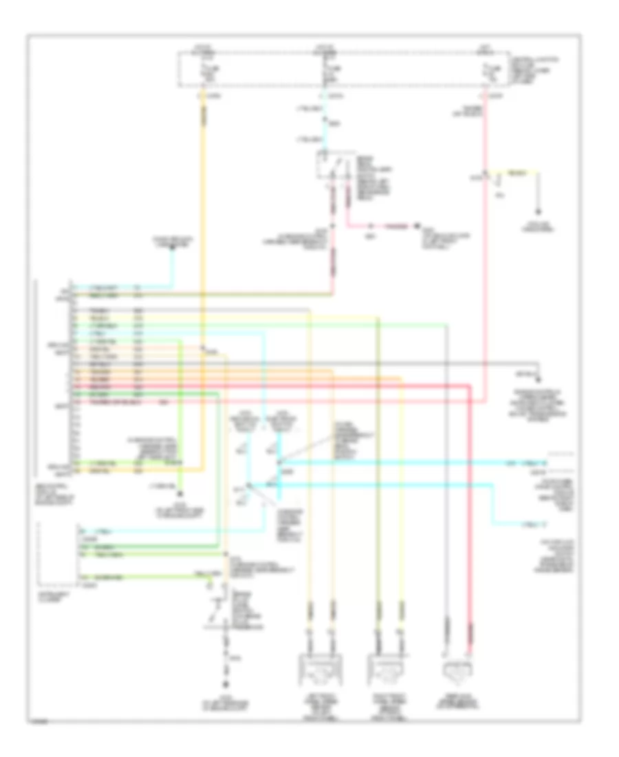
List of elements for Anti-lock Brakes Wiring Diagram for Ford F450 Super Duty 2003:
- (in engine control harness, near breakout for c144)
- (in engine control harness, near breakout for left headlight) s159
- (in main harness, near breakout to brake pedal position switch)
- 4x4 high/low indicator switch (near digital transmission range sensor)
- 6.0l
- Abs control module (at left side of engine compt)
- Brake fluid level switch (on brake fluid reservoir)
- Brake pedal position (bpp) switch (behind left side of dash, above brake pedal)
- C220b
- C220c
- C270a
- C270f
- C270m
- C281b
- Central junction box (cjb) (behind lower left side of dash)
- Computer data lines system
- Cooling fans system
- Engine controls, wiper/washer, instrument cluster, cruise control, sound, transmissions systems
- Four-wheel drive control module (behind right side of dash)
- Fuse 10a
- Fuse 60a
- G100 (at left rear side of engine compt)
- G105 (at left front side of engine compt)
- G300 (on vehicle floor, in left front footwell)
- Ground
- Hot at all times
- Hot in run
- Instrument cluster
- Iso
- Left front wheel speed sensor (at left front wheel)
- Nca
- Rear axle speed sensor (on differential)
- Red/pnk
- Right front wheel speed sensor (at right front wheel)
- S102
- S109
- S111
- S163
- S178 (in engine control harness, near breakout for g101)
- S201
- S228
- S259
- Vbatt
- Vpwr
- With electronic shift on the fly
- With mechanical shift on the fly
 English