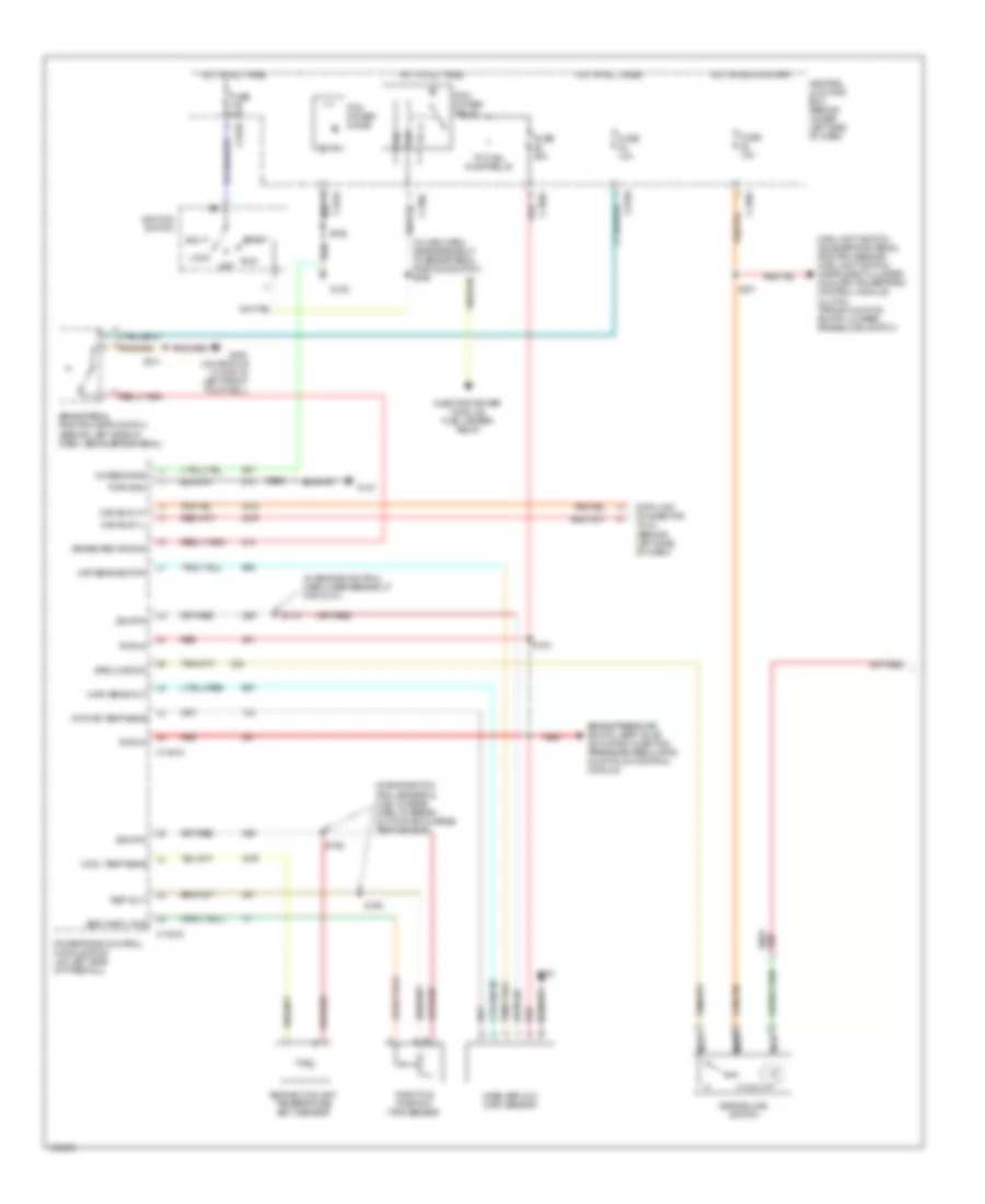
TRANSMISSION
4WD Wiring Diagram for Ford F450 Super Duty 2003

List of elements for 4WD Wiring Diagram for Ford F450 Super Duty 2003:
- (in backup light switch to rear light feed harn, near breakout to c1220)
- (left side of engine compt) abs control module
- (left side of transmission) digital transmission range sensor
- (pick-up)
- 4wd hi
- 4wd hi ind
- 4wd lo
- 4wd lo ind
- 4wd sw
- 87a
- Auxiliary relay box 3 (left rear side of engine compartment)
- Bpp sw
- Brake pedal position switch (behind left side of dash, above brake pedal)
- C135
- C220b
- C270a
- C270h
- C270m
- C281a
- C281b
- C281c
- C350a
- C350b
- Central junction box (lower left side of dash)
- Clutch pedal position switch
- Computer data lines connector
- Data link connector (behind center of dash)
- Dtr sensor, park brake relay, gas: speed control servo, dsl: vacuum pump motor
- Electronic shift-on-the-fly (esof) solenoid (right side of engine compt)
- Esof sol
- Excursion: pats module, eatc module
- Exterior lights system
- Four-wheel drive control module (behind right side of dash)
- Four-wheel drive switch
- Fuse 10a
- Fuse 15a
- Fuse 30a
- G100 (left rear side of engine compt)
- G201 (behind left side of dash)
- G300 (at floor, in left front footwell)
- Ground
- Hi to lo
- Hot at all times
- Hot in run
- Hot in run or acc
- Hot in run or start
- Hot in start
- Ign (st)
- Ign (st/run)
- Illum
- Instrument cluster
- Instrument cluster, windshield wiper motor, pickup: fuel tank selector switch
- Interior lights system
- Iso bus
- Lo to hi
- Main light switch, accelerator pedal position sensor, main light switch, instrument cluster, auxiliary powertrain control module, grade/load switch, clutch triple function switch jumper, overdrive cancel switch
- Motor 2
- Motor 3
- Motor 4
- Motor 5
- Nuet sens
- Off
- Pickup
- Red
- Ref volt
- Reverse
- S124
- S199
- S201
- S205 (behind left side of dash)
- S225 (behind instrument cluster)
- S228
- S250
- S253 (main harn, at breakout for instrument cluster)
- S254
- S255
- S257
- S271
- S275
- Shift sol
- Transfer case assembly
- Transfer case high to low relay
- Transfer case low to high relay
- Vpwr
- Vss in
- Vss out
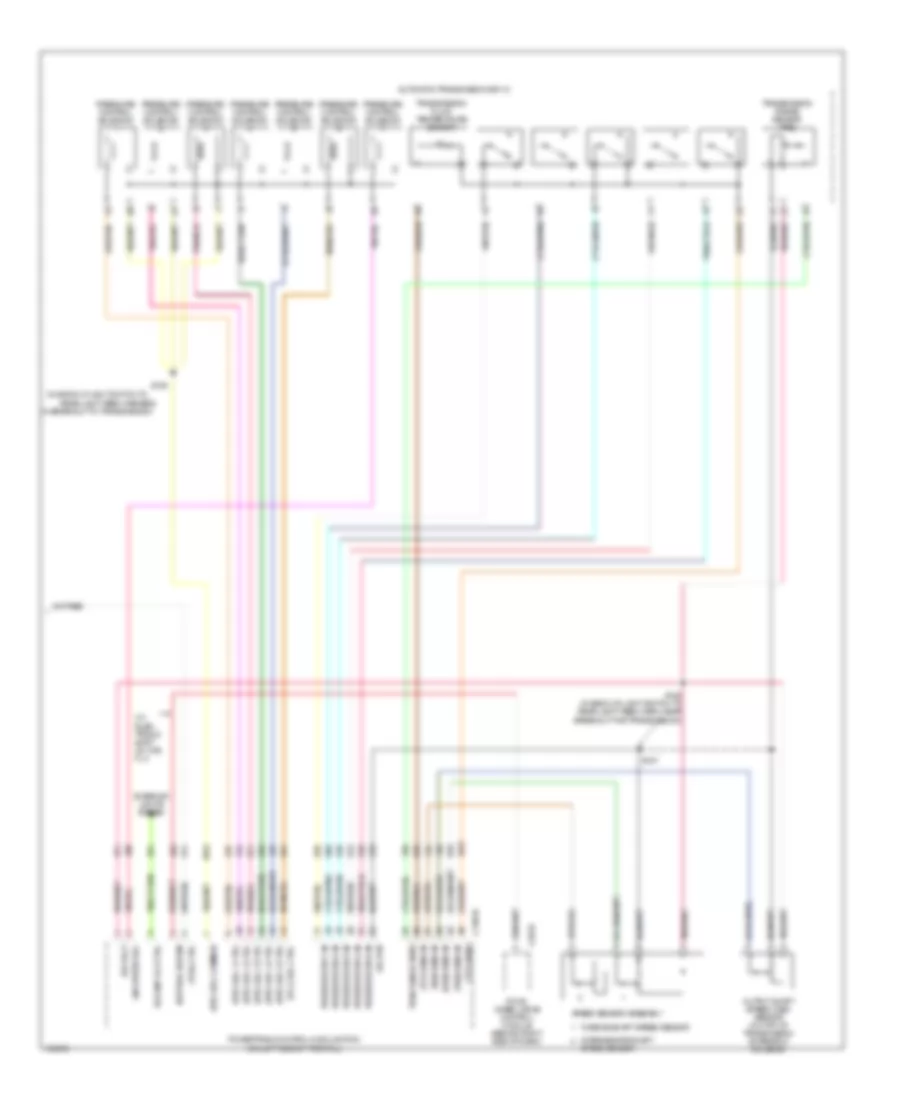
6.0L DIESEL
6.0L Diesel, A/T Wiring Diagram (1 of 2) for Ford F450 Super Duty 2003
List of elements for 6.0L Diesel, A/T Wiring Diagram (1 of 2) for Ford F450 Super Duty 2003:
- (in engine con- trol sensor & fuel charge harn, at break- out for air charge temp sensor)
- (in engine control harn, near breakout for g101)
- (in main harn, near breakout to brake pedal position switch) s224
- (maf) sens out
- Acc
- Brake ped pos sw
- Brake pedal position (bpp) switch (behind left side of dash, above brake pedal)
- Brake pressure switch, egr valve actuator, injection pressure regulator, glow plug control module
- C1381a
- C1381c
- C270a
- C270h red
- Can bus 1h
- Can bus 1l
- Central junction box (behind lower left side of dash)
- Chassis gnd
- Cool temp sens
- Data link connector (dlc) (behind left side of dash)
- Egr thrtl pos
- Engine coolant temperature (ect) sensor
- Fuse 10a
- Fuse 20a
- Fuse 30a
- G100
- G101
- G300 (on vehicle floor, in left front footwell)
- Grade/load switch
- Grd/load sw
- Hot at all times
- Hot in run or start
- Ignition switch
- Injector driver module, fuel heater relay
- Intk air temp sens
- Lock
- Maf sens sig rtn
- Main light switch, accelerator pedal position sensor, main light switch, instrument cluster, auxiliary powertrain control module, clutch triple function switch jumper, grade/load switch
- Mass airflow (maf) sensor
- Nca
- Off
- Pcm power diode
- Pcm power relay
- Powertrain control module (pcm) (on left side of firewall)
- Pwr gnd
- Pwr in
- Red
- Ref volt
- Run
- S101
- S106
- S114
- S123
- S162
- S190
- S192
- S271
- Sig rtn
- Start
- Throttle position (tps) sensor
- To fuel pump relay
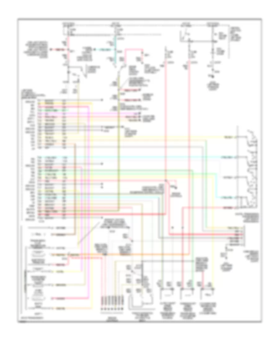
6.0L Diesel, A/T Wiring Diagram (2 of 2) for Ford F450 Super Duty 2003
List of elements for 6.0L Diesel, A/T Wiring Diagram (2 of 2) for Ford F450 Super Duty 2003:
- (epc) sol 1 ctrl
- (epc) sol 2 ctrl
- (epc) sol 3 ctrl
- (epc) sol 4 ctrl
- (epc) sol 5 ctrl
- (epc) sol common
- (in back-up light switch to
- (iss) sens in
- (on left side of firewall)
- (oss) sens in
- (tcc) sol ctrl
- (tcil) ctrl
- (tft) sens
- (tft) sens in
- (tss) sens in
- (w/ elec- tronic shift on the fly)
- Automatic transmission 5r110
- C1381b
- C281b
- Exterior lights system
- Four- wheel drive control module (behind right side of dash)
- In breakout to transmission)
- Intermediate shaft
- Line press sol
- Neutral sw sen
- Output shaft speed (oss) sensor (on top of transmission extension housing)
- Powertrain control module (pcm)
- Pressure control solenoid
- Pressure sw 1 in
- Pressure sw 2 in
- Pressure sw 3 in
- Pressure sw 4 in
- Pressure sw 5 in
- Rear light feed harness,
- Ref volt
- Rev lmp rly ctrl
- S127
- S128 (in back-up light switch to rear light feed harn, near breakout for transmission)
- S129
- Sig rtn
- Speed sensor
- Speed sensor assembly
- Tran range sens
- Transmission fluid temperature sensor
- Transmission range sensor (trs)
- Turbine shaft speed sensor
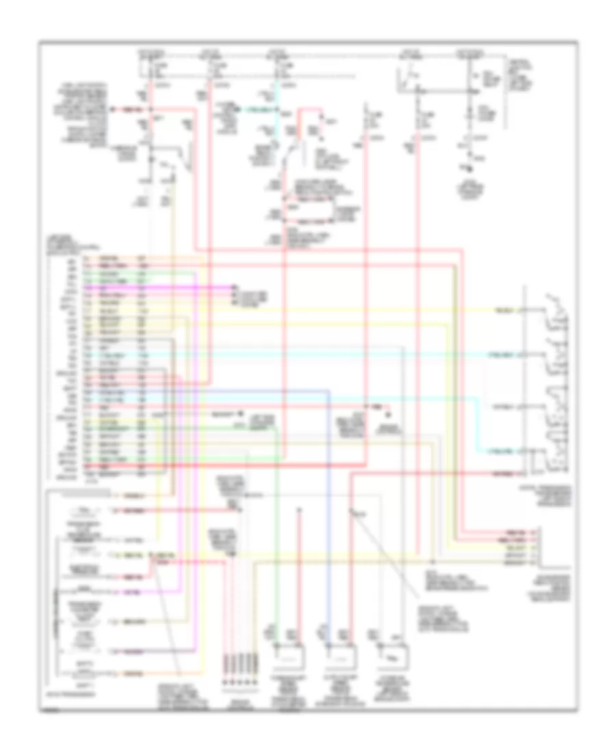
6.8L
6.8L, A/T Wiring Diagram for Ford F450 Super Duty 2003
List of elements for 6.8L, A/T Wiring Diagram for Ford F450 Super Duty 2003:
- (5.4l calif) s133
- (backup light sw to rear light feed harn, near breakout for auto trans module)
- (eng cntrl harn, near breakout for brake pressure switch)
- (eng cntrl harn, near breakout for g100 s122
- (in main harn, near breakout to brake pedal position switch)
- (left side of firewall) powertrain control module (pcm)
- 4-wheel drive control module, pats module, eatc module
- 4r100 transmission
- Bpp sw
- Brake pedal position switch
- C175
- C270a
- C270f
- C270h
- Ccs
- Central junction box (lower left side of dash)
- Cht
- Coast clutch
- Computer data lines system
- Control solenoids
- Cylinder head temperature sender (on right cylinder head)
- Data
- Digital transmission range sensor (left side of transmission)
- Electronic pressure
- Engine controls
- Epc
- Exterior lights system
- Fuse 10a
- Fuse 20a
- G100 (left rear of engine compt)
- G101 (left rear of engine compt)
- G300 (at floor, in left front footwell)
- Ground
- Hot at all times
- Hot in run or start
- Iat
- Maf
- Main light switch, accelerator pedal position sensor, main light switch, instrument cluster, overdrive cancel switch
- Mass airflow sensor (left front of engine compt)
- Nca
- Near breakout for g101)
- Oss
- Output shaft speed sensor (top of transmission extension housing)
- Overdrive cancel switch
- Pcm power diode
- Pcm power relay
- R p
- Red
- S106
- S114 (eng cntrl narn near breakout for g101)
- S123 (in eng cntrl harn, near breakout for powertrain control module)
- S132
- S138
- S139
- S162
- S170 (calif)
- S201
- S205
- S228
- S271
- Scp (+)
- Scp (-)
- Shift 1
- Shift 2
- Sig rtn
- Ss1
- Ss2
- Tcc
- Tcil
- Tcs
- Tft
- Throttle position (tp) sensor (on throttle body)
- Tr1
- Tr2
- Tr3
- Tr4
- Transmission converter clutch
- Transmission fluid temperature sensor
- Tss
- Turbine shaft speed sensor (top of transmission at converter housing)
- Vpwr
- Vref
7.3L DIESEL
7.3L Diesel, A/T Wiring Diagram for Ford F450 Super Duty 2003
List of elements for 7.3L Diesel, A/T Wiring Diagram for Ford F450 Super Duty 2003:
- (backup light switch to rear light feed harn, near breakout for auto trans module)
- (eng cntrl harn, near breakout for g100) s122
- (eng cntrl harn, near breakout for g101)
- (left side of engine compt)
- (left side of firewall) powertrain control module (pcm)
- (main harn, near breakout to brake pedal position switch)
- 4-wheel drive control, pats & eatc module
- 4r100 transmission
- Accelerator pedal position sensor (on accelerator pedal support)
- App
- Bpp sw
- Brake pedal position switch
- C175
- C270a
- C270f
- C270g
- C270h
- Ccs
- Central junction box (lower left side of dash)
- Coast clutch
- Computer data lines system
- Control solenoids
- Data
- Digital transmission range sensor (left side of transmission)
- Electronic pressure
- Engine controls
- Epc
- Exterior lights system
- Fuse 10a
- Fuse 20a
- G100 (left rear of engine compt)
- G101
- G300 (at floor, in left front footwell)
- Ground
- Hot at all times
- Hot in run or start
- Iat
- Intake air temperature sensor (left side of engine compt)
- Main light switch, accelerator pedal position sensor, main light switch, instrument cluster, auxiliary powertrain control module, clutch triple function switch jumper, overdrive cancel switch
- Nca
- Near breakout for g101)
- Oss
- Output shaft speed sensor (top of transmission extension housing)
- Overdrive cancel switch
- Pcm power diode
- Pcm power relay
- R p
- Red
- S106
- S114
- S123 (eng cntrl harn, near breakout for g100)
- S138
- S139
- S162
- S170 (eng cntrl harn, near breakout for brake pressure switch)
- S201
- S205
- S228
- S271
- Scp (+)
- Scp (-)
- Shift 1
- Shift 2
- Sig rtn
- Ss1
- Ss2
- Tcc
- Tcil
- Tcs
- Tft
- Tr1
- Tr2
- Tr3
- Tr4
- Transmission converter clutch
- Transmission fluid temperature sensor
- Tss
- Turbine shaft speed sensor (top of transmission, at converter housing)
- Vbatt
- Vpwr
- Vref