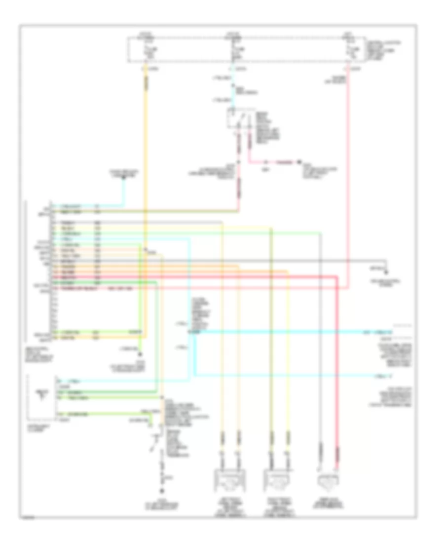
ANTI-LOCK BRAKES
Anti-lock Brakes Wiring Diagram for Ford F450 Super Duty 2004
List of elements for Anti-lock Brakes Wiring Diagram for Ford F450 Super Duty 2004:
- (in main harness, near breakout to brake pedal position switch) s259
- (or 1155)
- 4x4 high/low indicator switch (w/o electronic shift on the fly) (top of transfer case)
- Abs control module (at left side of engine compt)
- Abs ind
- Bpp in
- Brake fluid level switch (on brake fluid reservoir)
- Brake pedal position switch (behind left side of dash, above brake pedal)
- C220b
- C220c
- C270a
- C270f
- C270m
- C281b
- Central junction box (cjb) (behind lower left side of dash)
- Computer data lines system
- Cruise control system
- Four wheel drive control module (w/ electronic shift on the fly) (behind right side of dash)
- Fuse 10a
- Fuse 60a
- G100 (at left rear side of engine compt)
- G105 (at left front side of engine compt)
- G300 (on vehicle floor, in left front footwell)
- Ground
- Hi/low
- Hot at all times
- Hot in run
- Ind ctrl
- Instrument cluster
- Iso
- Left front wheel speed sensor (at left front wheel assembly)
- Nca
- Rear axle speed sensor (on differential)
- Red/pnk
- Right front wheel speed sensor (at right front wheel assembly)
- S102
- S159
- S163
- S178 (gasoline: near breakout for g101) (diesel: near breakout for junction block on left front fender)
- S201
- S228 (excursion)
- Sw in
- Vbatt
- Vpwr
- Vss
 English