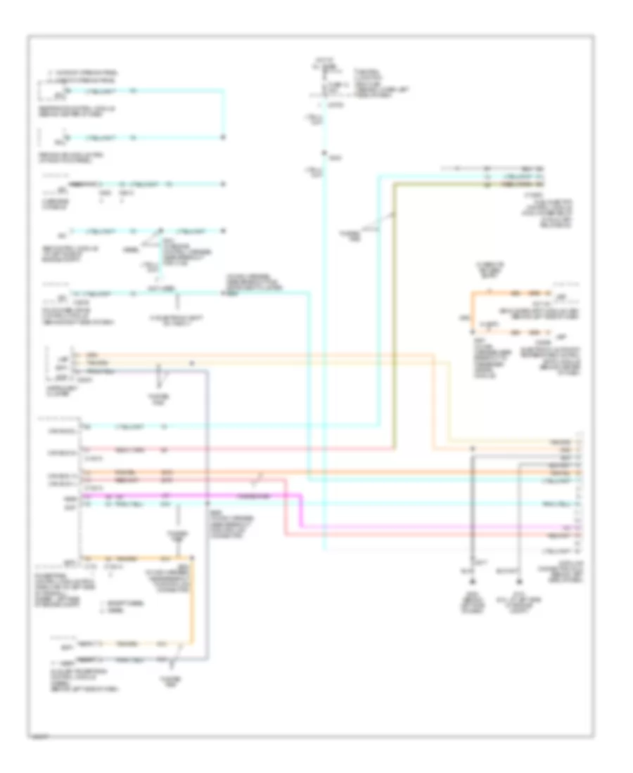
COMPUTER DATA LINES
Computer Data Lines Wiring Diagram for Ford F450 Super Duty 2004
List of elements for Computer Data Lines Wiring Diagram for Ford F450 Super Duty 2004:
- (in main harness, near breakout for instrument cluster) s225
- (not used)
- Abs control module (at left side of engine compt)
- Auxiliary powertrain control module (diesel) (behind left side of dash)
- C1381a
- C1381c
- C1388c
- C175
- C2113c
- C220a
- C228b
- C270d
- C281b
- C9013
- C930
- Can bus 1h
- Can bus 1l
- Can bus 2h
- Can bus 2l
- Central junction box (cjb) (behind lower left side of dash)
- Data link connector (dlc) (behind left side of dash)
- Diesel
- Electronic automatic temperature control (eatc) module (behind center of dash)
- Except diesel
- Feps
- Four wheel drive control module (behind right side of dash)
- Fuel injector control module (ficm) power relay (in auxiliary relay box 5)
- Fuse 12 20a
- G101 (6.0l: at left side of engine compt)
- G202 (behind left side of dash)
- Hot at all times
- Instrument cluster
- Iso
- Nca
- Overhead console
- Parking aid module (pam) (at right kick panel)
- Powertrain control module (pcm) (gasoline: on left side of firewall) (diesel: left side of engine compt)
- Restraints control module (behind center of dash)
- S217
- S242
- S247 (in main harness,near breakout to passenger air bag module)
- S284 (in main harness, near breakout for data link connector)
- S286 (in main harness, near breakout for data link connector)
- Scp+
- Scp-
- Twisted pair
- Ubp
- Vehicle security module (vsm) (behind left side of dash)
- W/ eatc
- W/ electronic shift on the fly
- W/ remote keyless entry
- W/ roof opening panel
- W/0 roof opening panel
 English