ANTI-LOCK BRAKES
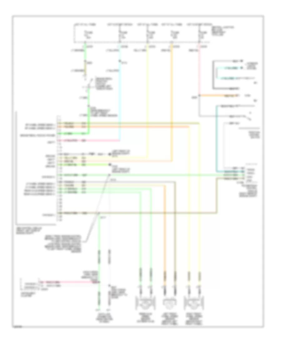
Anti-lock Brakes Wiring Diagram for Ford Pickup F150 2006
List of elements for Anti-lock Brakes Wiring Diagram for Ford Pickup F150 2006:
- (early prod: engine control sensor harn, near breakout to abs control module, late prod: engine control sensor harn, near breakout to left front wheel speed sensor)
- (left front of engine compt) g110
- (main wiring harn, near breakout to c2026) s288
- Abs control module (front left side of engine compt)
- Brake pedal pos sw power
- Brake pedal position switch (under left side of dash)
- C175b
- C220a
- C270b
- C270c
- C270d
- C270f
- Can bus (+)
- Can bus (-)
- Can+
- Can-
- Central junction box (cjb) (near right "a" pillar)
- Data link connector (near center of dash)
- Fuse 10a
- Fuse 20a
- Fuse 40a
- Fuse 5a
- G108 (left front of engine compt)
- Ground
- Hot at all times
- Hot in start or run
- Instrument cluster
- Interior lights system
- Left front wheel speed sensor (behind left front wheel)
- Lf wheel speed sens (+)
- Lf wheel speed sens (-)
- Nca
- Powertrain control module (right rear of engine compt)
- Rear axle speed sens (+)
- Rear axle speed sens (-)
- Rear axle speed sensor (on rear axle)
- Rf wheel speed sens (+)
- Rf wheel speed sens (-)
- Right front wheel speed sensor (behind right front wheel)
- S109 (near breakout to left front wheel speed sensor)
- S112
- S116
- S117
- S118
- S220
- S225
- S287 (main wiring harn, near breakout to c2026)
- Tracil
- Tracs
- Traction control switch
- Vbatt
 English