POWER DISTRIBUTION
Power Distribution Wiring Diagram (1 of 3) for Ford Pickup F150 2006

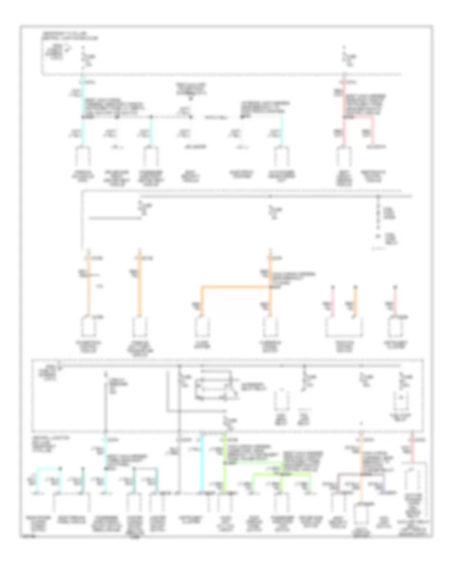
List of elements for Power Distribution Wiring Diagram (1 of 3) for Ford Pickup F150 2006:
- (body main wiring harn, at breakout for c270j)
- (diagram 1 of 3)
- (main wiring harn, near breakout to c254)
- (main wiring harness, near breakout to autolamp/ sunload sensor) (w/ body security module) s266
- (seat control feed jumper harness, under driver seat) s315
- (w/ 4x4) s105
- (w/ memory)
- A/c clutch relay
- Abs control module
- Audio unit
- Auto a/c
- Autolamp/ sunload sensor
- Auxiliary relay box 1 (left side of engine compt)
- Battery
- Battery saver relay
- Body security module
- Brake pedal position switch
- C102a
- C102b
- C175b
- C205a
- C228a
- C270b
- C270c
- C270d
- C270e
- C270f
- C270g
- C270h
- C270j
- C270m
- C270n
- C270p
- C290a
- C294a
- C3008a
- C341c
- Central junction box (cjb) (near right ``a" pillar)
- Console 1 power point
- Console 2 power point
- Data link connector (dlc)
- Driver seat module
- Driver side front seat adjust switch
- Dvd player
- Early prod: eng ctrl sensor harn, near break- out to g102 late prod: eng ctrl sensor harn, near break- out to right rear of engine compt
- Electronic automatic temperature control (eatc) module
- Electronic manual temperature control (emtc) module
- Exterior rear view mirror switch
- From fuse 5 a
- Front blower motor relay
- Front cigar lighter
- Fuse 10a
- Fuse 15a
- Fuse 20a
- Fuse 25a
- Fuse 30a
- Fuse 40a
- Fuse 5a
- Fuse 7.5a
- G202 (in left front footwell)
- G206 (right kick panel)
- Generator
- Horn relay
- Indicator flasher relay
- Instrument panel power point
- Integrated wheel ends solenoid (w/ 4x4)
- Main light switch
- Manual a/c
- Nca
- Of roof at c339) s338
- Passenger side front seat adjust switch
- Power folding mirror relay
- Powertrain control module (pcm)
- Red
- Red/ s211
- S120 (alternator rectifier harness, near breakout to fusible link a, b or c)
- S201
- S203
- S209
- S236
- S345 (w/ memory) (body main harness near right side of instrument panel near inertia fuel shutoff switch)
- S355
- S380
- Satellite audio receiver
- Starter motor
- Starter relay
- Subwoofer
- To fuse 109 (diagram 2 of 3)
- To fuse 6 (diagram 1 of 3)
- Trailer electronic brake control module
- Trailer tow battery charge relay
- Trailer tow parking lamp relay
- Trailer tow reversing lamp relay
- W/ satellite
Power Distribution Wiring Diagram (2 of 3) for Ford Pickup F150 2006
List of elements for Power Distribution Wiring Diagram (2 of 3) for Ford Pickup F150 2006:
- (diagram 1 of 3)
- (engine control sensor harness, in breakout to auxiliary box 1) s111
- (engine control sensor harness, near breakout to evap canister vent valve)
- (near right "a" pillar) central junction box (cjb)
- (near right ``a" pillar) central junction box (cjb)
- (not used)
- A/c high pressure switch
- Abs control module
- Acc
- Adjustable pedal switch (w/o memory)
- Audio unit
- Auto a/c
- Auxiliary power point
- Auxiliary relay box 1 (left side of engine compartment)
- Brake pedal position switch
- Brake shift interlock
- C220a
- C220b
- C228a
- C270b
- C270c
- C270d
- C270e
- C270f
- C270g
- C270h
- C270k
- C270m
- C290a
- C294a
- C341b
- Clockwise (cw) motor 4x4 relay
- Counterclockwise (ccw) motor 4x4 relay
- Dash)
- Daytime running lamps (drl) enable relay
- Deactivator switch
- Digital transmission range (dtr) sensor
- Digital transmission range (dtr) sensor (a/t)
- Driver seat module
- Driver side front heated seat module
- Driver side front seat adjust switch
- Electronic automatic temperature control (eatc) module
- Electronic manual temperature control (emtc) module
- Floor shifter
- From fuse 10 b
- Front blower motor relay
- Fuse 10a
- Fuse 20a
- Fuse 30a
- Fuse 40a
- Fuse 5a
- G303 (left kick panel)
- Heated positive crankcase ventilation
- Heated rear window relay
- Ignition switch
- Indicator flasher relay
- Instrument cluster
- Key in ignition switch
- Key removal inhibit solenoid
- Manual a/c
- Nca
- Off/lock
- Passenger air bag deactivation (pad) indicator
- Passenger side front heated seat module
- Pcm power relay
- Red
- Reversing lamps switch (m/t)
- Run
- S112
- S299 (main wiring harness, near breakout to brake shift interlock)
- S905
- Start
- Tan/ red
- To fuse (diagram 3 of 3)
- To fuse 18 (diagram 3 of 3)
- To fuse 21 (diagram 3 of 3)
- Trailer tow battery charge relay
- W/ memory
- W/o memory
- Windshield wiper motor
- Xlt, fx4, lariat
Power Distribution Wiring Diagram (3 of 3) for Ford Pickup F150 2006
List of elements for Power Distribution Wiring Diagram (3 of 3) for Ford Pickup F150 2006:
- (body main harness wires near right kick panel) s344
- (body main wiring harness, near right side of instrument panel at inertia fuel shutoff (ifs) switch) s228
- (diagram 2 of 3)
- (interior lamp harness, near breakout to electronic compass)
- (main wiring harness, under dash, near breakout to instrument panel power point) s285
- (near right "a" pillar) central junction box (cjb)
- 4.2l
- Accessory delay relay
- Audio unit (xlt, fx4, lariat)
- Auto-dimmer inside mirror unit
- Auxiliary relay box 1 (left side of engine compt)
- Body security module
- C175b
- C202b
- C205a
- C220b
- C270b
- C270d
- C270e
- C270f
- C270h
- C270j
- C270n
- C290a
- C3008a
- C3008b
- C310a
- C504b
- Central junction box (cjb) (near right "a" pillar)
- Circuit breaker 30a
- Daytime running lamps (drl) enable relay
- Driver side door lock switch
- Driver side front heated seat module
- Electronic compass
- Floor shifter
- Fog lamp relay
- From auxiliary power point (diagram 2 of 3)
- From c fuse 102 (diagram 2 of 3)
- From fuse 27 d
- Fuel pump diode
- Fuel pump relay
- Fuse 10a
- Fuse 15a
- Fuse 20a
- Fuse 5a
- High beam relay
- Instrument cluster
- Main light switch
- Master window adjust switch
- Master window adjust switch (regular cab)
- Multi- function switch
- Overdrive cancel switch
- Parking aid module (pam)
- Passenger side door lock switch
- Passenger side front heated seat module
- Passenger side window adjust switch (regular cab)
- Passive anti-theft transceiver module
- Powertrain control module
- Rear power sliding window switch
- Restraints control module
- Roof opening panel module
- Roof opening panel switch
- S909
- Seat weight sensor module
- Traction control switch