COMPUTER DATA LINES
Computer Data Lines Wiring Diagram, with Stripped Chassis for Ford E-350 Super Duty XL 2014

List of elements for Computer Data Lines Wiring Diagram, with Stripped Chassis for Ford E-350 Super Duty XL 2014:
- (engine control sensor wiring harness, near breakout to c110)
- (engine control sensor wiring harness, near breakout to c110) s111
- (main wiring harness, near breakout to traction control switch)
- (main wiring harness, near breakout to traction control switch) s258
- (mounted to front of left chassis frame rail) anti-lock brake system (abs) module
- 6.8l
- Battery junction box (bjb) (mounted to front of left chassis frame rail)
- C1551b
- C175b
- C2280b
- C291
- Cdb08
- Data link connector (dlc) (left center of dash)
- Except 6.8l
- Feps
- Fuse 15a
- G205 (left side of dash)
- G207 (center of dash)
- Gd114
- Gd133
- Hot at all times
- Hs can +
- Hs can -
- Hs can+
- Hs can-
- Instrument panel cluster (ipc)
- Micro
- Ms can+
- Ms can-
- Powertrain control module (pcm) (above front center of engine)
- S250
- S255 (main wiring harness, near breakout to traction control switch)
- S256
- S257 (main wiring harness, near breakout to traction control switch)
- Sbb42
- Smart junction box (sjb) (left side of dash)
- Vdb04
- Vdb05
- Vdb06
- Vdb07
- Vdbo4
- Vdbo5
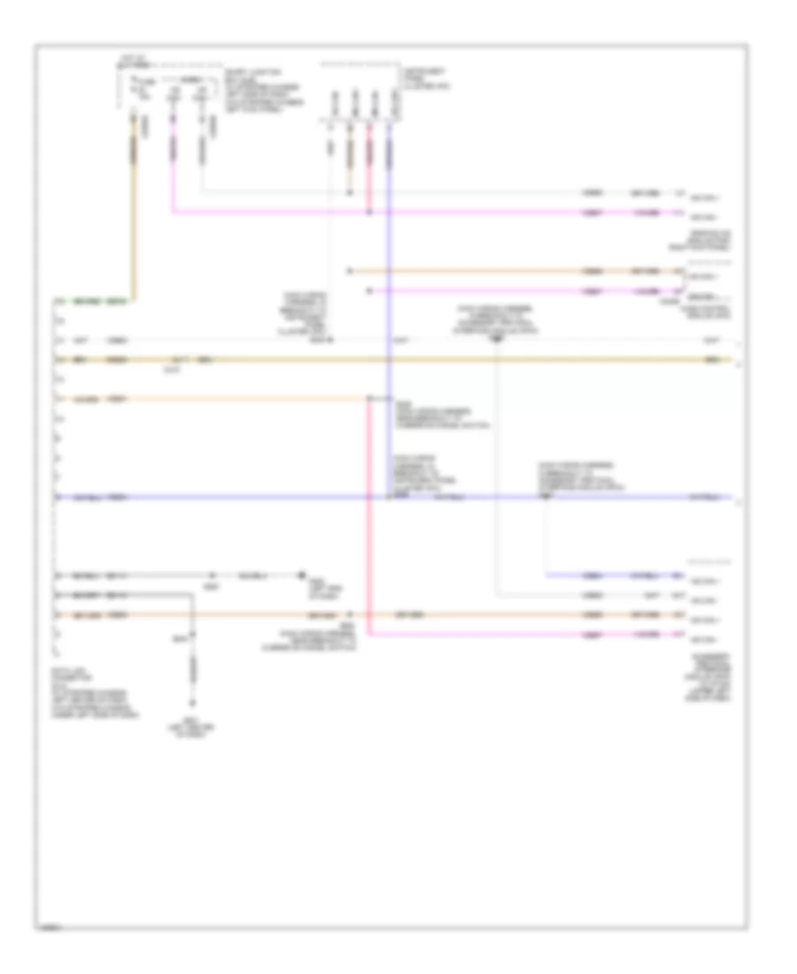
Computer Data Lines Wiring Diagram, without Stripped Chassis with Navigation (1 of 2) for Ford E-350 Super Duty XL 2014
List of elements for Computer Data Lines Wiring Diagram, without Stripped Chassis with Navigation (1 of 2) for Ford E-350 Super Duty XL 2014:
- (main wiring harness, in breakout to accessory protocol interface module (apim)) s266
- (main wiring harness, in breakout to accessory protocol interface module (apim)) s267
- (main wiring harness, in breakout to instrument panel cluster (ipc)) s224
- (main wiring harness, in breakout to instrument panel cluster (ipc)) s225
- (main wiring harness, near breakout to overdrive cancel switch)
- Accessory protocol interface module (apim) (w/ sync) (upper left side of dash)
- Audio control module (acm)
- C219
- C2280a
- C2280b
- C240b
- Cdb08
- Data link connector (dlc) (w/ stripped chassis: left center of dash) (w/o stripped chassis: under left side of dash)
- Fuse 15a
- G201 (left center of dash)
- G202 (left end of dash)
- Gd114
- Gd115
- Hot at all times
- Hs can +
- Hs can -
- Instrument panel cluster (ipc)
- Micro
- Ms can +
- Ms can -
- Parking aid module (pam) (right kick panel)
- S228
- S229 (main wiring harness, near breakout to overdrive cancel switch)
- S263
- S264
- Sbp20
- Smart junction box (sjb) (w/ stripped chassis: left side of dash) (w/o stripped chassis: left kick panel)
- Vdb04
- Vdb05
- Vdb06
- Vdb07
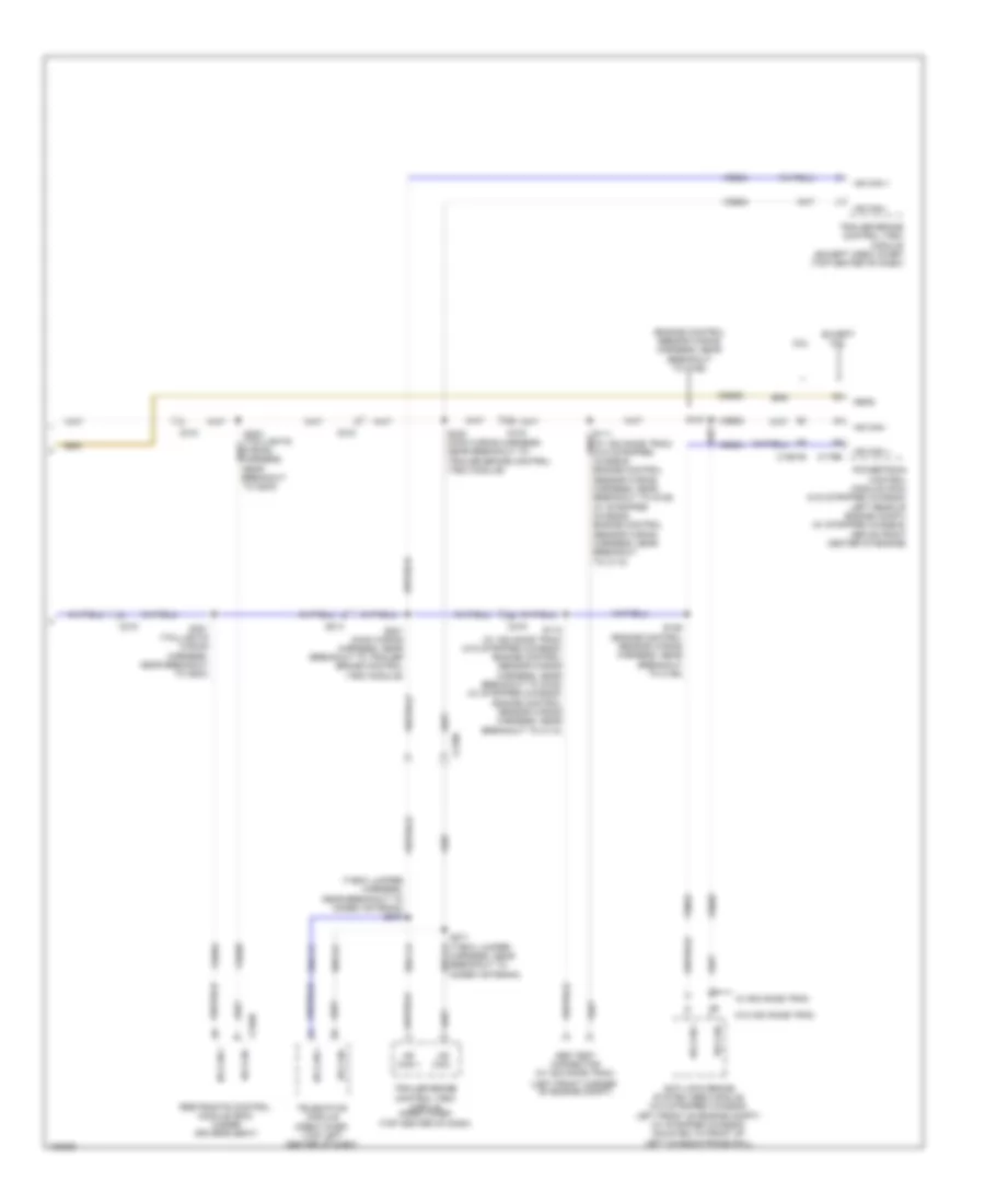
Computer Data Lines Wiring Diagram, without Stripped Chassis with Navigation (2 of 2) for Ford E-350 Super Duty XL 2014
List of elements for Computer Data Lines Wiring Diagram, without Stripped Chassis with Navigation (2 of 2) for Ford E-350 Super Duty XL 2014:
- (engine control sensor wiring harness, near breakout to c192)
- (left front corner
- (main wiring harness, near breakout to trailer brake control (tbc) module)
- (t-box jumper harness, near breakout to modem antenna) s270
- 6.8l
- Abs test connector (w/ advance trac)
- Anti-lock brake system (abs) module (w/o stripped chassis: left front of engine compt) (w/ stripped chassis: mounted to front of left chassis frame rail)
- C1551b
- C175b
- C210
- C2108
- C219
- C310b
- Cdb08
- Except 6.8l
- Feps
- Harness, near breakout to modem antenna)
- Hs can +
- Hs can -
- Hsc1-a
- Hsc1-c
- Hsc2-c
- Of engine compt)
- Powertrain control module (pcm) (w/o stripped chassis: left rear of engine compt) (w/ stripped chassis: above front center of engine)
- Restraints control module (rcm) (under driver's seat)
- S112 (w/ advance trac) (w/o stripped chassis: engine control sensor wiring harness, near breakout to g105) (w/ stripped chassis: engine control sensor wiring harness, near breakout to c110)
- S126 (engine control sensor wiring harness, near breakout to c192)
- S127
- S221
- S222 (main wiring harness, near breakout to trailer brake control (tbc) module)
- S271 (t-box jumper hsc2-a
- S301 (taillights wiring harness, near breakout to g203)
- S302
- Telematics module (crew chief) (top left center of dash)
- Trailer brake control (tbc) module (crew chief) (top center of dash)
- Trailer brake control (tbc) module (except crew chief) (top center of dash)
- Vdb04
- Vdb05
- W/ advance trac
- W/o advance trac
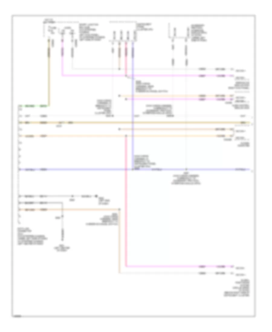
Computer Data Lines Wiring Diagram, without Stripped Chassis without Navigation (1 of 2) for Ford E-350 Super Duty XL 2014
List of elements for Computer Data Lines Wiring Diagram, without Stripped Chassis without Navigation (1 of 2) for Ford E-350 Super Duty XL 2014:
- (main wiring harness, in breakout to accessory protocol interface module (apim)) s266
- (main wiring harness, in breakout to instrument panel cluster (ipc)) s224
- (main wiring harness, in breakout to instrument panel cluster (ipc)) s225
- (main wiring harness, near breakout to overdrive cancel switch)
- (right kick panel)
- Accessory protocol interface module (apim) (w/ sync) (upper left side of dash)
- Audio control module (acm)
- C219
- C2280a
- C2280b
- C2408b
- C240b
- Cdb08
- Data link connector (dlc) (w/o stripped chassis: under left side of dash) (w/ stripped chassis: left center of dash)
- Fuse 15a
- G201 (left center of dash)
- G202 (left end
- Gd114
- Gd115
- Global positioning system module (gpsm) (w/ sync) (behind right side of instrument cluster)
- Hot at all times
- Hs can +
- Hs can -
- In dash computer
- Instrument panel cluster (ipc)
- Micro
- Ms can +
- Ms can -
- Of dash)
- Parking aid module (pam)
- S228
- S229 (main wiring harness, near breakout to overdrive cancel switch)
- S263
- S264
- S267 (main wiring harness, in breakout to accessory protocol interface module (apim))
- Sbp20
- Smart junction box (sjb) (w/o stripped chassis: left kick panel) (w/ stripped chassis: left side of dash)
- Vdb04
- Vdb05
- Vdb06
- Vdb07
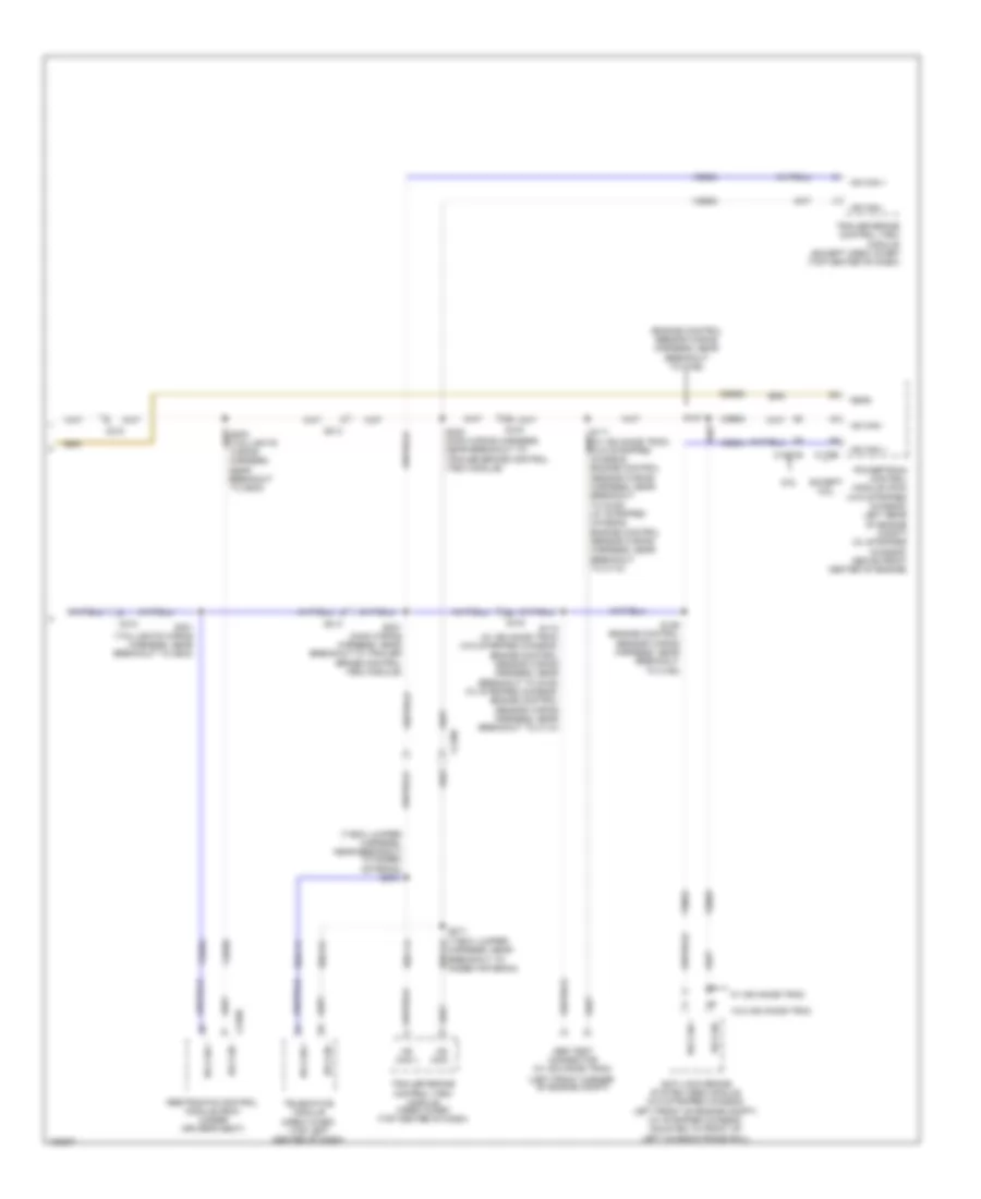
Computer Data Lines Wiring Diagram, without Stripped Chassis without Navigation (2 of 2) for Ford E-350 Super Duty XL 2014
List of elements for Computer Data Lines Wiring Diagram, without Stripped Chassis without Navigation (2 of 2) for Ford E-350 Super Duty XL 2014:
- (engine control sensor wiring harness, near breakout to c192)
- (left front corner
- (main wiring harness, near breakout to trailer brake control (tbc) module)
- (t-box jumper harness, near breakout to modem antenna)
- (taillights wiring harness, near breakout to g203)
- 6.8l
- Abs test connector (w/ advance trac)
- Anti-lock brake system (abs) module (w/o stripped chassis: left front of engine compt) (w/ stripped chassis: mounted to front of left chassis frame rail)
- C1551b
- C175b
- C210
- C2108
- C219
- C310b
- Cdb08
- Except 6.8l
- Feps
- Harness, near breakout to modem antenna)
- Hs can +
- Hs can -
- Hsc1-a
- Hsc1-c
- Hsc2-c
- Of engine compt)
- Powertrain control module (pcm) (w/o stripped chassis: left rear of engine compt) (w/ stripped chassis: above front center of engine)
- Restraints control module (rcm) (under driver's seat)
- S112 (w/ advance trac) (w/o stripped chassis: engine control sensor wiring harness, near breakout to g105) (w/ stripped chassis: engine control sensor wiring harness, near breakout to c110)
- S126 (engine control sensor wiring harness, near breakout to c192)
- S127
- S221
- S222 (main wiring harness, near breakout to trailer brake control (tbc) module)
- S270
- S271 (t-box jumper hsc2-a
- S301 (taillights wiring harness, near breakout to g203)
- S302
- Telematics module (crew chief) (top left center of dash)
- Trailer brake control (tbc) module (crew chief) (top center of dash)
- Trailer brake control (tbc) module (except crew chief) (top center of dash)
- Vdb04
- Vdb05
- W/ advance trac
- W/o advance trac