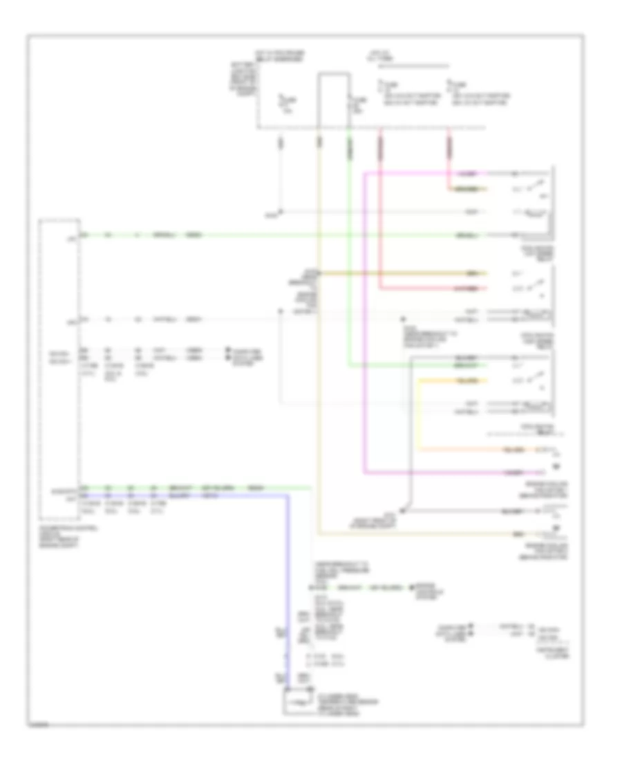
COOLING FAN
Cooling Fan Wiring Diagram for Ford Pickup F150 2011
List of elements for Cooling Fan Wiring Diagram for Ford Pickup F150 2011:
- (3.5l)
- (3.7l)
- (5.0l & 6.2l)
- (5.0l)
- (6.2l)
- (near breakout to fuel rail pressure sensor) (3.5l) s162
- (w/ svt raptor)
- (w/o svt raptor)
- 50a
- Battery junction box (bjb) (front of of engine compt)
- C1026
- C133
- C1381b
- C1381e
- C1551b
- C1551e
- C175b
- C175e
- Ce202
- Cec01
- Cht
- Computer data lines system
- Cooling fan high speed relay
- Cooling fan low speed relay
- Cooling fan relay
- Cylinder head temperature sensor (rear of right cylinder head)
- E sig rtn
- Engine controls system
- Engine cooling fan motor 1 (behind radiator)
- Engine cooling fan motor 2 (behind radiator)
- Fuse 10a
- Fuse 25a
- Fuse 40a
- G101 (right front of of engine compt)
- Hfc
- Hot at all times
- Hot w/ pcm power relay energized
- Hs can +
- Hs can -
- Hs can+
- Hs can-
- Instrument cluster
- Lfc
- Powertrain control module (right rear of engine compt)
- Re405
- S105
- S173 (6.2l & 5.0l) (5.0l: near breakout to c1019) (6.2l: near breakout to c133)
- S183 (near breakout to engine cooling fan motor 1)
- S197 (near breakout to engine cooling fan motor 1)
- Vdb04
- Vdb05
- Ve712
 English