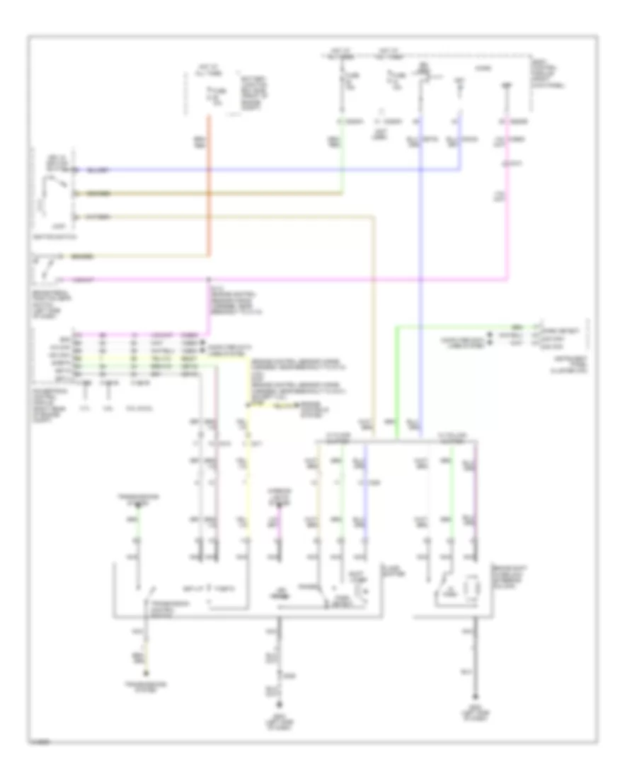
SHIFT INTERLOCK
Shift Interlock Wiring Diagram for Ford Pickup F150 2011
List of elements for Shift Interlock Wiring Diagram for Ford Pickup F150 2011:
- (engine control sensor wiring harness, near breakout to g110) (3.5l) s167 (engine control sensor wiring harness, near breakout to g101) (except 3.5l) s169
- (not used)
- 3.5l
- 3.7l
- 5.0l & 6.2l
- Battery junction box (bjb) (front of engine compt)
- Body control module (right kick panel)
- Boo
- Bpp
- Brake pedal position (bpp) switch (left side of dash)
- Brake shift interlock (steering column)
- Bsi (fet)
- C1381b
- C1551b
- C175b
- C210
- C211
- C213
- C2280a
- C2280b
- C2280c
- C328
- Ccb08
- Cet42
- Cet43
- Computer data lines system
- Engine controls system
- Floor shifter
- Fuse 10a
- Fuse 15a
- G202 (left side of dash)
- G203 (left side of dash)
- Ha can-
- Hot at all times
- Hs can+
- Hs can-
- Ignition switch
- In park
- Instrument panel cluster (ipc)
- Interior lights system
- Key in
- Key in ignition switch
- Led panel
- Lock
- Micro
- Nca
- Park detect
- Powertrain control module (right rear of engine compt)
- Range
- Re407
- S112 (engine control sensor wiring harness, near breakout to c110)
- S329
- Shift lock
- Sigrtn
- Sst-d
- Sst-u
- Transmission control switch
- Transmissions system
- Vdb04
- Vdb05
- W/ column shifter
- W/ floor shifter
 English