CRUISE CONTROL
Cruise Control Wiring Diagram, Diesel for Ford Econoline E250 1997

List of elements for Cruise Control Wiring Diagram, Diesel for Ford Econoline E250 1997:
- (engine harn, left rear of eng compt)
- Accel set/
- Brake on/off (boo) switch (on brake pedal bracket)
- Brake pres- sure switch (bottom of brake master cyl- inder)
- C224
- Clock- spring assembly (top of steering column)
- Coast
- Door locks system
- Engine comp- artment fuse box
- Fuse 15a
- G202 (behind upper left left side of i/p)
- G202 (behind upper left side of i/p)
- Horn relay (engine compt fuse box)
- Horn switch
- Hot at all times
- Hot in run
- I/p fuse panel
- Illumination
- Instrument cluster
- Interior lights system
- Nca
- Off
- Ohms
- Powertrain control module (pcm) (left rear of engine compt)
- Resume
- S116
- S129
- S135 (engine harn, near breakout to fuel octane sensor)
- S139
- S205
- S224 (lower i/p harn, near breakout to 76 pin conn, on cowl, left rear of engine compt)
- Speed control switch assembly (top of steering column)
- Speedo
- Vehicle speed sensor (vss) (on left side of trans)
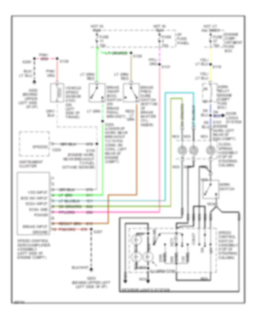
Cruise Control Wiring Diagram, Gasoline for Ford Econoline E250 1997
List of elements for Cruise Control Wiring Diagram, Gasoline for Ford Econoline E250 1997:
- (engine harn, left rear of eng compt)
- Accel set/
- Boo sw input
- Brake input
- Brake on/off (boo) switch (on brake pedal bracket)
- Brake pres- sure switch (bottom of brake master cyl- inder)
- C224
- Clock- spring assembly (top of steering column)
- Coast
- Door locks system
- Engine comp- artment fuse box
- Fuse 10a
- Fuse 15a
- G202 (behind upper left left side of i/p)
- G202 (behind upper left side of i/p)
- Ground
- Horn relay (engine compt fuse box)
- Horn switch
- Hot at all times
- Hot in run
- I/p fuse panel
- Illumination
- Instrument cluster
- Interior lights system
- Nca
- Off
- Ohms
- Power
- Resume
- S116
- S129
- S131
- S135 (engine harn, near breakout to fuel octane sensor)
- S139
- S205
- S207
- S224 (lower i/p harn, near breakout to 76 pin conn, on cowl, left rear of engine compt)
- Scsa gnd
- Scsa input
- Speed control servo/amplifier assembly (left side of engine compt)
- Speed control switch assembly (top of steering column)
- Speedo
- Vehicle speed sensor (vss) (on left side of trans)
- Vss input