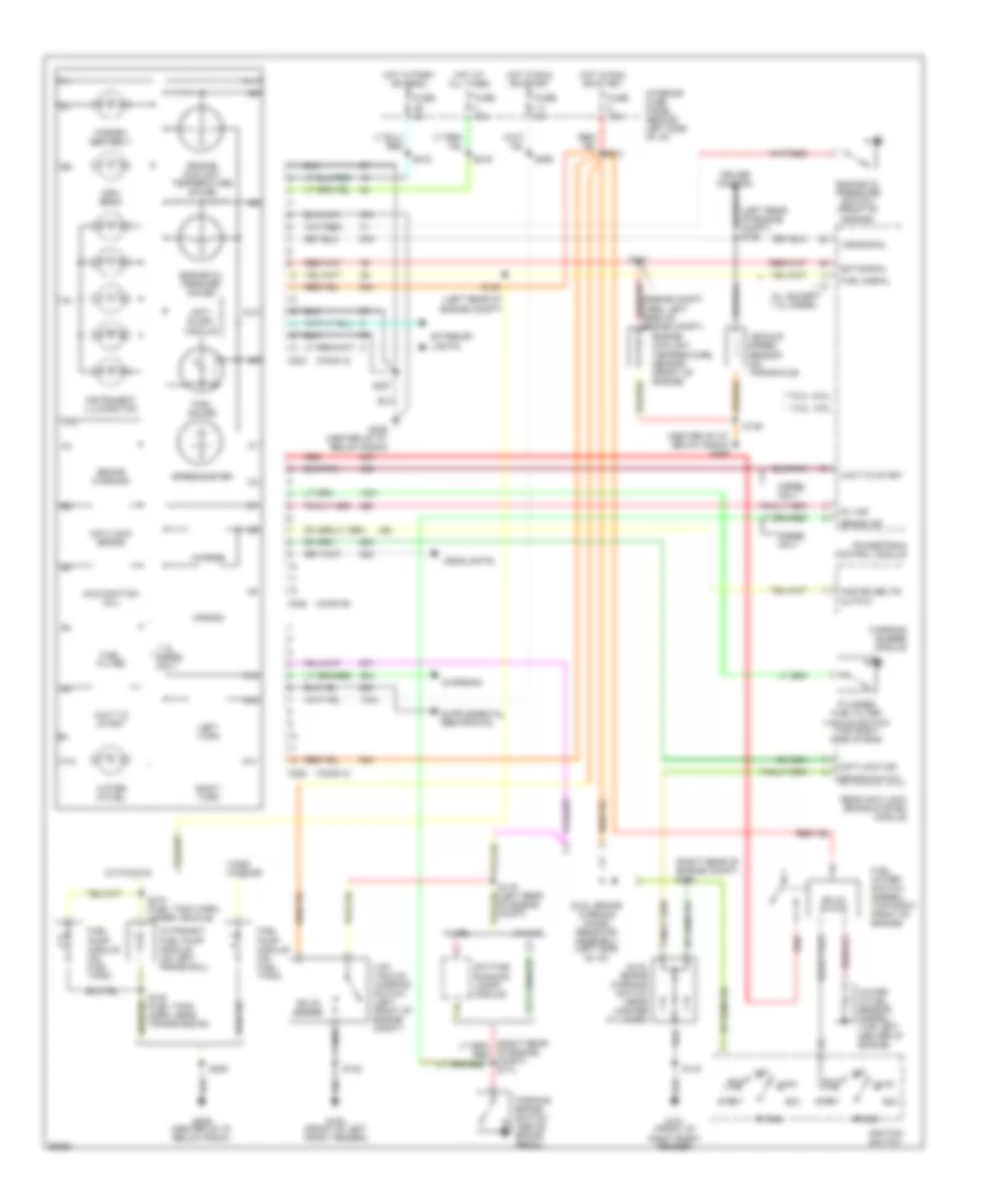
INSTRUMENT CLUSTER
Instrument Cluster Wiring Diagram, 4 Wheel ABS for Ford Econoline E250 1997

List of elements for Instrument Cluster Wiring Diagram, 4 Wheel ABS for Ford Econoline E250 1997:
- (center of i/p, below radio) g206
- (conn a)
- (conn b)
- (conn c)
- (i/p harn, on top of steering column) s220
- (left rear of engine compt)
- (left rear of engine compt) s135
- (right rear of engine compt) s174
- * (4.2l, 4.6l)
- * 12
- ** (5.4l, 6.8l)
- ** 9
- 4wabs relay (center of i/p)
- 7.3l
- A10
- A11
- A13
- A14
- A15
- A16
- Acc
- Air bag
- All except 7.3l diesel
- All wheel anti-lock brake system module
- Anti- slosh module
- Anti-lock brake
- Anti-lock ind
- Brake ind
- Brake switch
- Brake warning
- C12
- C224
- C225
- Charge
- Charging
- Cruise control
- Cutaways
- Daytime running lamps module
- Diesel
- Diesel only
- Dual brake warning switch (near master cylinder)
- Ect signal
- Engine coolant temperature gauge
- Engine coolant temperature sensor (front of engine)
- Engine oil pressure switch (front of engine)
- Engine oil prssure gauge
- Exterior lights
- Fasten belts output
- Fasten seatbelt
- Fuel filter
- Fuel gauge
- Fuel pump module
- Fuel pump module (on fuel tank)
- Fuel signal
- Fuel water switch (diesel) (top right front of engine)
- Fuse 15a
- Fuse 5a
- G100 (front of left front fender)
- G101 (front of right front fender)
- G202 (left side of i/p)
- G206 (center of i/p, below radio)
- Gnd
- Headlights
- High beam
- Hot at all times
- Hot in park or head
- Hot in run or start
- Ignition switch
- In-transit fuel pump module (on left frame rail)
- Instrument illumination
- Interior fuse panel (behind left side of i/p)
- Left turn
- Lock
- Low vacuum warning switch (left front of engine compt)
- Malfunction (mil)
- Mil ind
- Off
- Only
- Parking brake switch (above brake pedal)
- Plugged fuel filter vacuum switch (top right side of eng)
- Powertrain control module
- Red
- Relay ctrl
- Right turn
- Run
- S108 (fuel tank harn, near transmission)
- S119 (left rear of engine compt)
- S120
- S122
- S133
- S139
- S143
- S205
- S207
- S212
- S213
- S219
- S265
- S310 (fuel tank harn, under vehicle)
- Solid state
- Speedometer
- Start
- Vans/ wagons
- Vehicle speed sensor (on transaxle)
- Vss signal
- W/ drl
- W/o drl
- Wait to start
- Warning buzzer module
- Water in fuel
- Water in fuel sensor (top left center of engine)
Instrument Cluster Wiring Diagram, Rear Wheel ABS for Ford Econoline E250 1997
List of elements for Instrument Cluster Wiring Diagram, Rear Wheel ABS for Ford Econoline E250 1997:
- (center of i/p, below radio) g206
- (conn a)
- (conn b)
- (conn c)
- (left rear of engine compt)
- (left rear of engine compt) s135
- (right rear of engine compt) s132
- * (4.2l, 4.6l)
- * 12
- ** (5.4l, 6.8l)
- ** 9
- 7.3l
- A10
- A11
- A13
- A14
- A15
- A16
- Acc
- Air bag
- All except 7.3l diesel
- Anti- slosh module
- Anti-lock brake
- Anti-lock ind
- Brake ind
- Brake switch
- Brake warning
- C12
- C224
- C225
- Charge
- Charging
- Cruise control
- Cutaways
- Daytime running lamps module
- Diesel
- Diesel only
- Dual brake warning diode/ resistor assembly (left side of i/p)
- Dual brake warning switch (near master cylinder)
- Ect signal
- Engine coolant temperature gauge
- Engine coolant temperature sensor (front of engine)
- Engine oil pressure switch (front of engine)
- Engine oil prssure gauge
- Exterior lights
- Fasten belts output
- Fasten seatbelt
- Fuel filter
- Fuel gauge
- Fuel pump module (on fuel tank)
- Fuel signal
- Fuel water switch (diesel) (top right front of engine)
- Fuse 15a
- Fuse 5a
- G100 (front of left front fender)
- G101 (front of right front fender)
- G206 (center of i/p, below radio)
- Gnd
- Headlights
- High beam
- Hot at all times
- Hot in park or head
- Hot in run or start
- Ignition switch
- In-transit fuel pump module (on left frame rail)
- Instrument illumination
- Interior fuse panel (behind left side of i/p)
- Left turn
- Lock
- Low vacuum warning switch (left front of engine compt)
- Malfunction (mil)
- Mil ind
- Of engine compt) s174
- Off
- Only
- Parking brake switch (above brake pedal)
- Plugged fuel filter vacuum switch (top right side of eng)
- Powertrain control module
- Rear anti-lock brake system module
- Red
- Right turn
- Run
- S108 (fuel tank harn, near transmission)
- S119 (left rear of engine compt)
- S120
- S122
- S133
- S139
- S143
- S205
- S207
- S212
- S213
- S219
- S265
- S310 (fuel tank harn, under vehicle)
- Solid state
- Speedometer
- Start
- Vans/ wagons
- Vehicle speed sensor (on transaxle)
- Vss signal
- W/ drl
- W/o drl
- Wait to start
- Warning buzzer module
- Water in fuel
- Water in fuel sensor (diesel) (top left center of engine)