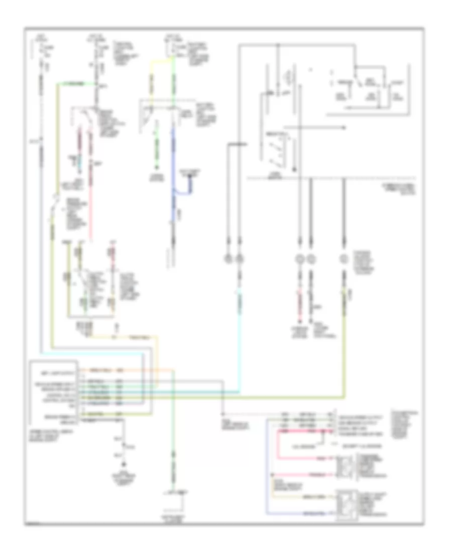
CRUISE CONTROL
Cruise Control Wiring Diagram for Ford Pickup F250 Super Duty 2002
List of elements for Cruise Control Wiring Diagram for Ford Pickup F250 Super Duty 2002:
- (4.2l engine)
- (except 4.2l engine)
- A/t
- Accel
- Air bag sliding contact (top of steering column)
- Anti-theft system
- Battery junction box (left side of engine compt)
- Brake pedal position (bpp) switch (under left side of dash)
- Brake press in
- Brake pressure switch (left rear corner of engine compt)
- C140
- C218b
- C220a
- C242
- C270b
- Central junction box (under left side of dash)
- Cluster
- Clutch pedal position (ccp) switch (on clutch pedal arm)
- Clutch triple function switch jumper (left side of dash)
- Coast
- Control sw gnd
- Control sw in
- Esof
- Fuse 15a
- Fuse 20a
- Fuse 5a
- G102 (right rear of engine compt)
- G200 (lower right kick panel)
- G201 (left front footwell)
- Ground
- Horn relay
- Horn switch
- Horns system
- Hot at all times
- Hot in run
- Ign
- Instrument
- Interior lights system
- M/t
- Nca
- Off
- Ohms
- Oss sensor output
- Output shaft speed (oss) sensor (on left side of transmission)
- Pnk
- Powertrain control module (on right side of engine compt)
- Resistor a
- Resume
- S102
- S112
- S138 (right rear of engine compt)
- S143 (left rear of engine compt)
- S208
- S274
- S297
- Set lamp output
- Set/
- Signal return
- Speed control servo (in left side of engine compt)
- Steering wheel/ speed control switch
- Transfer case sp sen
- Transfer case speed sensor (at left rear of transmission)
- Vehicle speed input
- Vehicle speed output
 English