SUPPLEMENTAL RESTRAINTS
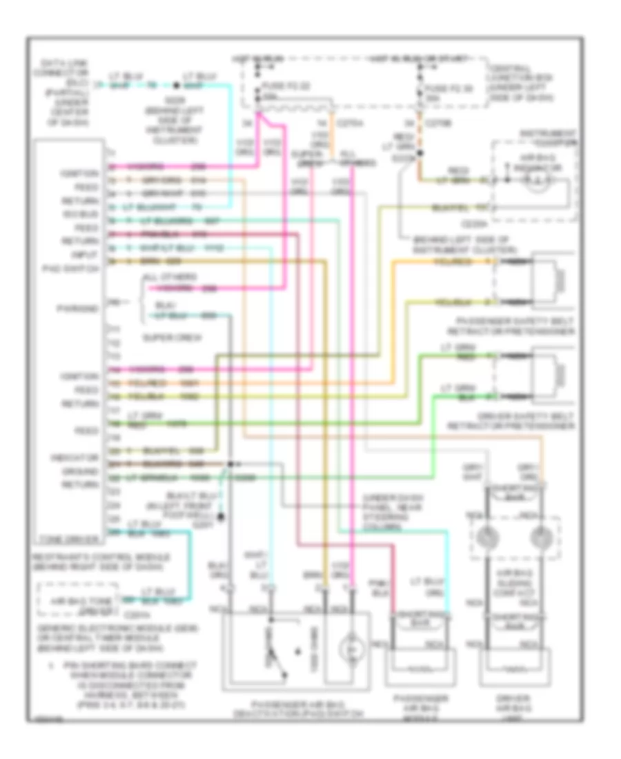
Supplemental Restraint Wiring Diagram for Ford Pickup F250 Super Duty 2002
List of elements for Supplemental Restraint Wiring Diagram for Ford Pickup F250 Super Duty 2002:
- (behind left side of instrument cluster)
- (in left front footwell) g201
- (partial) (under center of dash)
- (under dash panel, near steering column)
- 1000 ohms
- 500 ohms
- Air bag indicator
- Air bag sliding contact
- Air bag tone driver
- All others
- C201a
- C220a
- C270a
- C270b
- Central junction box (under left side of dash)
- Data link connector (dlc)
- Driver air bag unit
- Driver safety belt retractor pretensioner
- Feed
- Fuse f2.22 10a
- Fuse f2.30 30a
- Generic electronic module (gem) or central timer module (behind left side of dash)
- Ground
- Hot in run
- Hot in run or start
- Ignition
- Indicator
- Input
- Instrument cluster
- Iso bus
- Nca
- Pad switch
- Passenger air bag deactivation (pad) switch
- Passenger air bag module
- Passenger safety belt retractor pretensioner
- Pin shorting bars connect when module connector is disconnected from harness, between (pins 3-4, 6-7, 8-9 & 20-21)
- Pwr/gnd
- Restraints control module (behind right side of dash)
- Return
- S208
- S229 (behind left side of instrument cluster)
- S237
- Shorting bar
- Super crew
- Tone driver
 English