DEFOGGERS
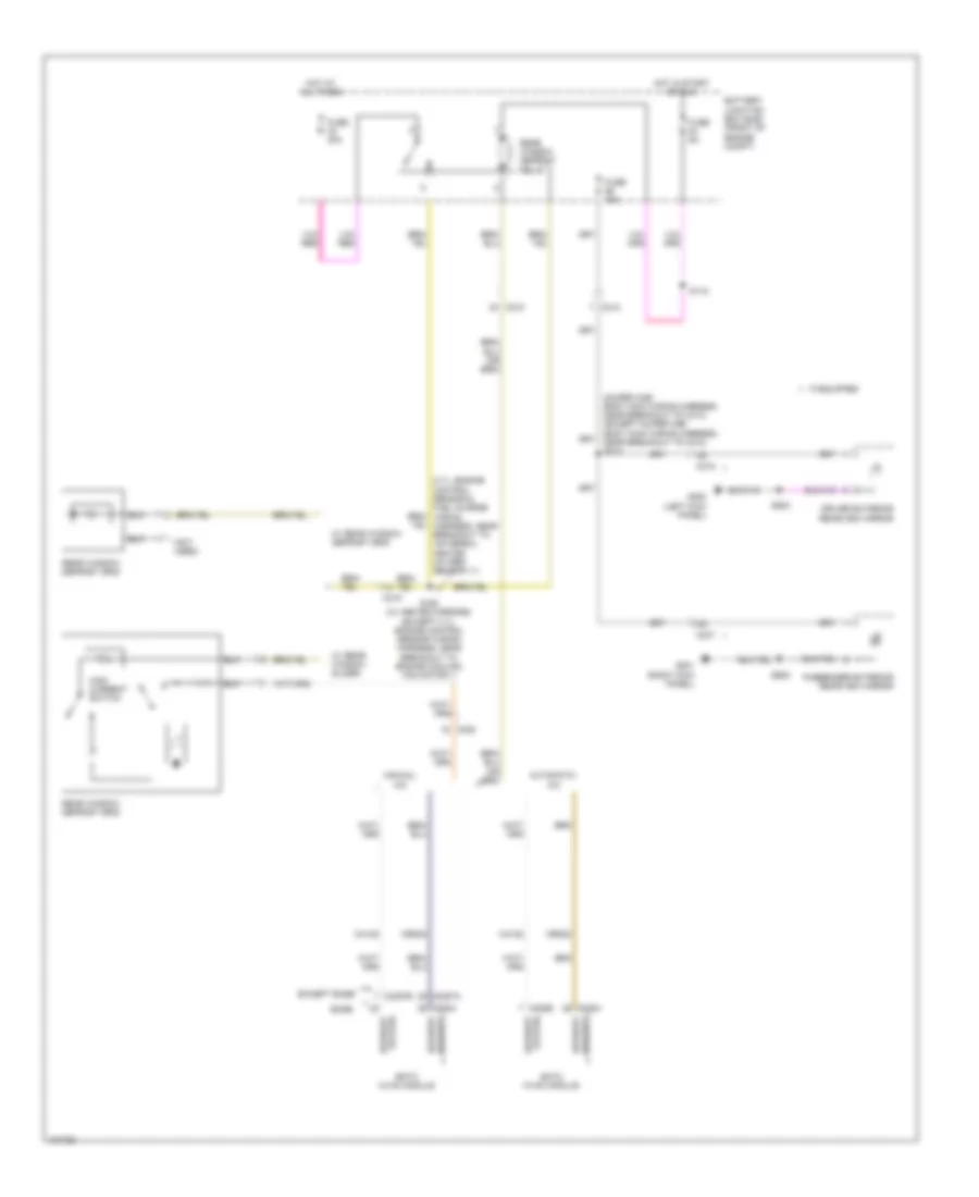
Defoggers Wiring Diagram for Ford F-150 XL 2014
List of elements for Defoggers Wiring Diagram for Ford F-150 XL 2014:
- (3.7l: engine control sensor & fuel charge wiring harness, near breakout to universal heated oxygen sensor 11)
- (not used)
- (super cab: body main wiring harness, near breakout to c313) (except super cab: body main wiring harness, near breakout to c312) s313
- Automatic a/c
- Base
- Battery junction box (bjb) (front of engine compt)
- C210
- C212
- C215
- C219
- C228a
- C228b
- C2357a
- C2357b
- C237
- C238
- C294a
- Ch122
- Crd02
- Defrost request
- Defrost status
- Driver exterior rearview mirror
- Eatc hvac module
- Emtc hvac module
- Except base
- Fuse 15a
- Fuse 40a
- Fuse 5a
- G200 (left kick panel)
- G201 (right kick panel)
- High current switch
- Hot at all times
- Hot in start or run
- If equipped
- Manual a/c
- Passenger exterior rearview mirror
- Rear window defrost grid
- Rear window defrost relay
- S118
- S160 (w/ heated mirrors) (except 3.7l: engine control sensor wiring harness, near breakout to engine cooling fan motor 1)
- S500
- S600
- W/ rear window defrost grid
- W/ rear window slider
 English