ENGINE PERFORMANCE
3.5L TURBO
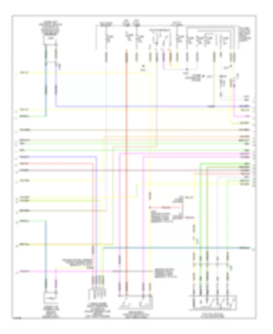
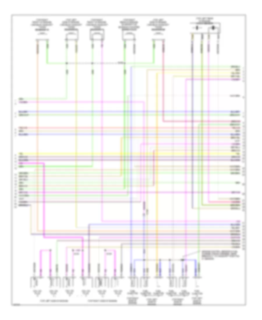
3.5L Turbo, Engine Performance Wiring Diagram (1 of 6) for Ford F-150 XL 2014

List of elements for 3.5L Turbo, Engine Performance Wiring Diagram (1 of 6) for Ford F-150 XL 2014:
- (fuel tank assembly) fuel tank pressure (ftp) sensor
- A/c pressure transducer (right front of engine compt)
- Aat
- Accelerator pedal position (app) sensor (top of brake pedal assembly)
- Accr
- Acpt
- Air conditioning system
- App1
- App2
- Apprtn
- Apprtn2
- Appvref1
- Appvref2
- Body control module (right kick panel)
- Bpp
- C146
- C1551b
- C1581
- C192
- C214
- C2280f
- Cact
- Canv
- Cbb53
- Ccb08
- Cdc10
- Cdc12
- Cdc15
- Cdc35
- Cdc54
- Ce113
- Ce114
- Ce233
- Ce234
- Ce436
- Ce607
- Cec01
- Cec02
- Ch302
- Computer data lines system
- Cooling fans system
- Evapcp
- Fpc
- Fpm
- Fuse 10a
- Gencom
- Generator current sensor (right front corner of engine compt)
- Genmon
- Heated oxygen sensor (ho2s) 12 (engine exhaust pipe)
- Heated oxygen sensor (ho2s) 22 (engine exhaust pipe)
- Hfc
- Ho2s12
- Ho2s22
- Hot at all times
- Hs can +
- Hs can -
- Htr12
- Htr22
- Ispr
- Le136
- Le137
- Le230
- Le424
- Lfc
- Micro
- Passive anti-theft transceiver (ignition switch assembly)
- Pcm wake
- Pcm wake up (fet)
- Pcmrc
- Powertrain control module (pcm) (right rear of engine compt)
- Re136
- Re137
- Re145
- Re332
- Re405
- Re407
- S140
- S141
- S240 (engine control sensor wiring harness, near breakout to body control module)
- Sigrtn
- Smc
- Smcs
- Start
- Starting/ charging system
- Starting/charging system
- Vdb04
- Vdb05
- Ve225
- Ve518
- Ve701
- Ve702
- Ve731
- Ve733
- Ve750
- Vh433
- Vref
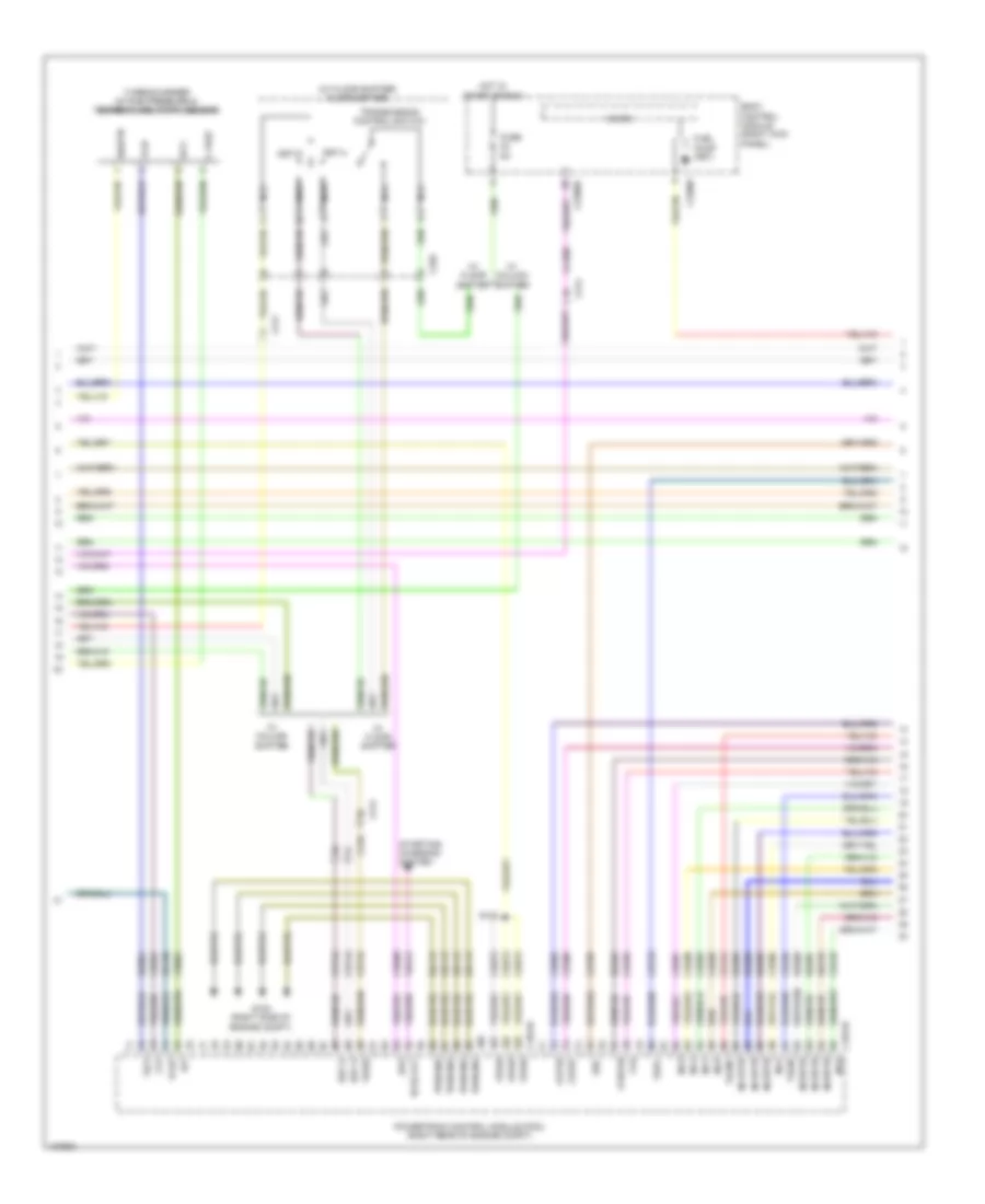
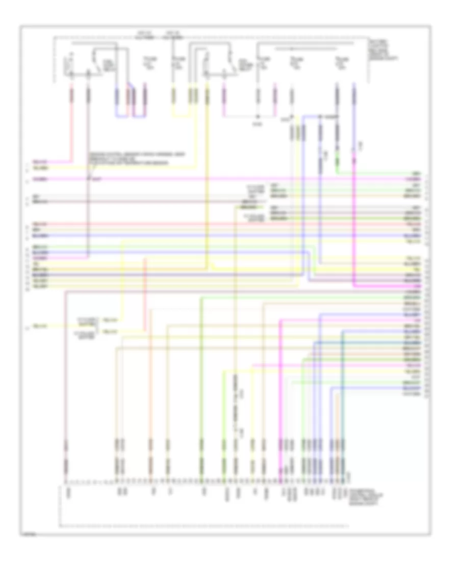
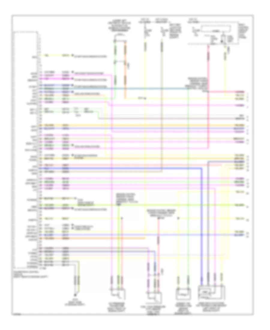
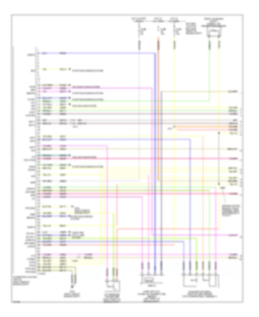
3.5L Turbo, Engine Performance Wiring Diagram (2 of 6) for Ford F-150 XL 2014
List of elements for 3.5L Turbo, Engine Performance Wiring Diagram (2 of 6) for Ford F-150 XL 2014:
- (engine control sensor wiring harness, near breakout to c110)
- (engine control sensor wiring harness, near breakout to g101) s169
- (under left center of vehicle) evaporative emission (evap) canister vent solenoid
- Ambient air temperature sensor (front of engine compt)
- Battery junction box (bjb) (front of engine compt)
- Brake pedal position (bpp) switch (left side of dash)
- C-vref
- C146
- C1581
- C211
- C264
- Cact
- Fuse 10a
- Fuse 15a
- Fuse 20a
- Fuse 25a
- Fuse 50a
- Fuse 5a
- Hot at all times
- Hot in run or start
- Nca
- Pcm power relay
- Power distribution system
- R/s
- S101
- S105
- S112
- S121
- S125
- S129
- S167 (engine control sensor wiring harness, near breakout to c110)
- Sigrtn
- Sst-d
- Sst-u
- Tcbp
- Tow haul switch (w/ column shifter)
- Tows
- Turbocharger boost pressure/ charge air cooler temperature sensor (left side of engine)
- W/ column shifter
- W/ floor shifter
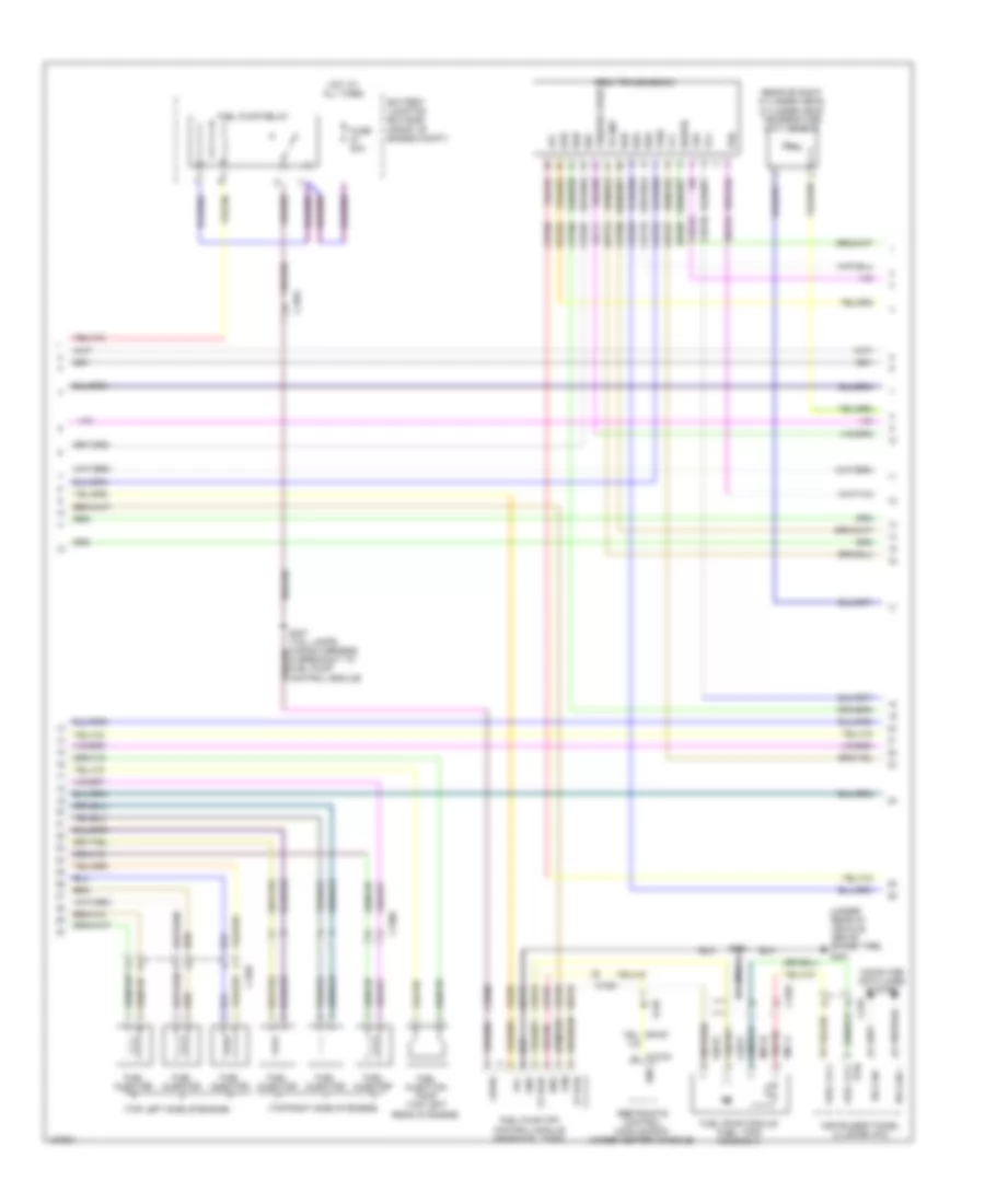
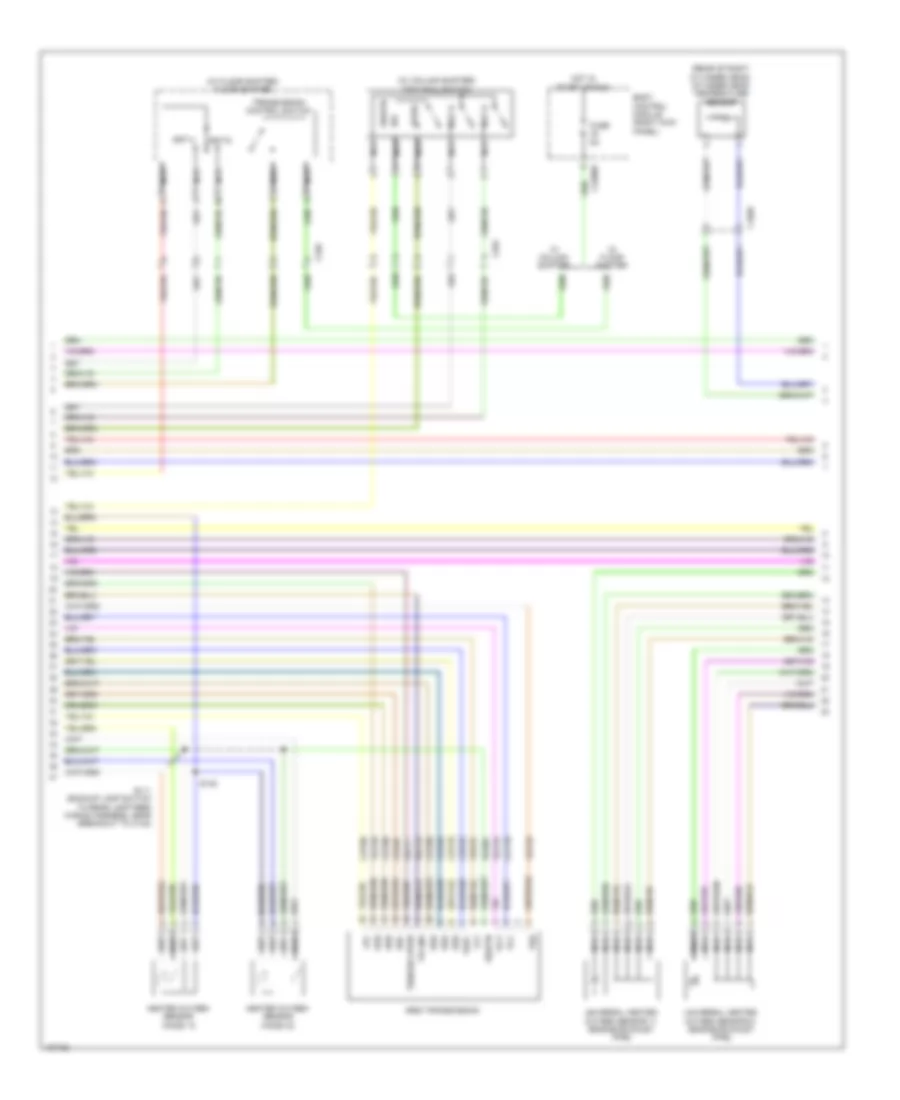
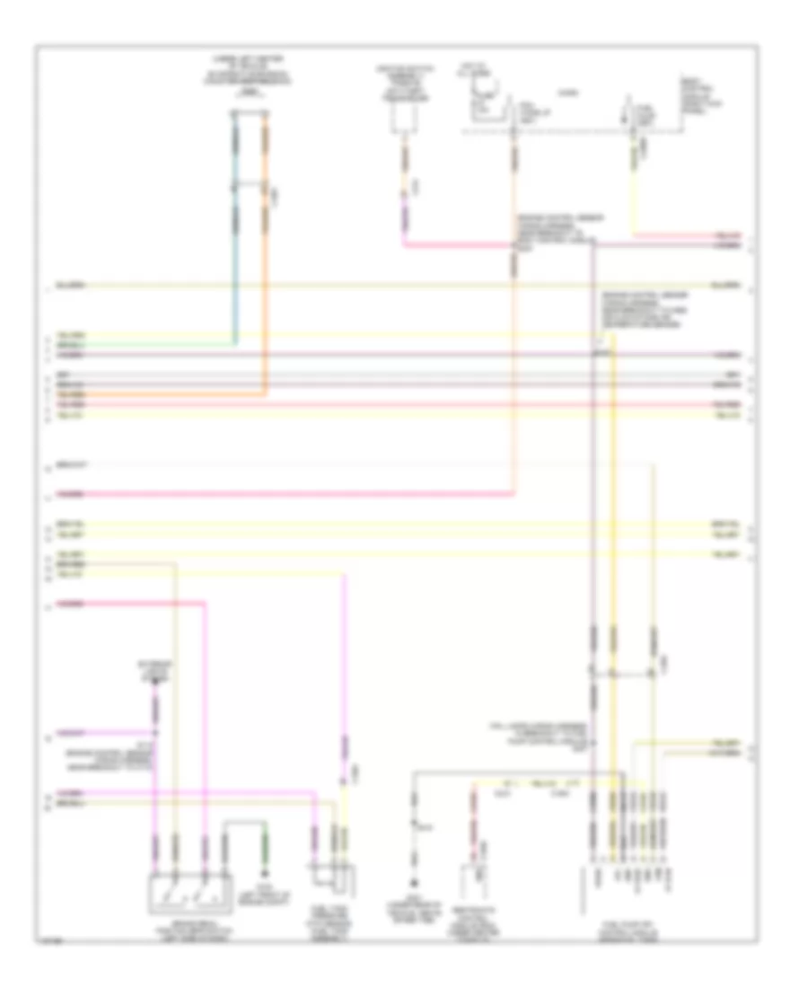
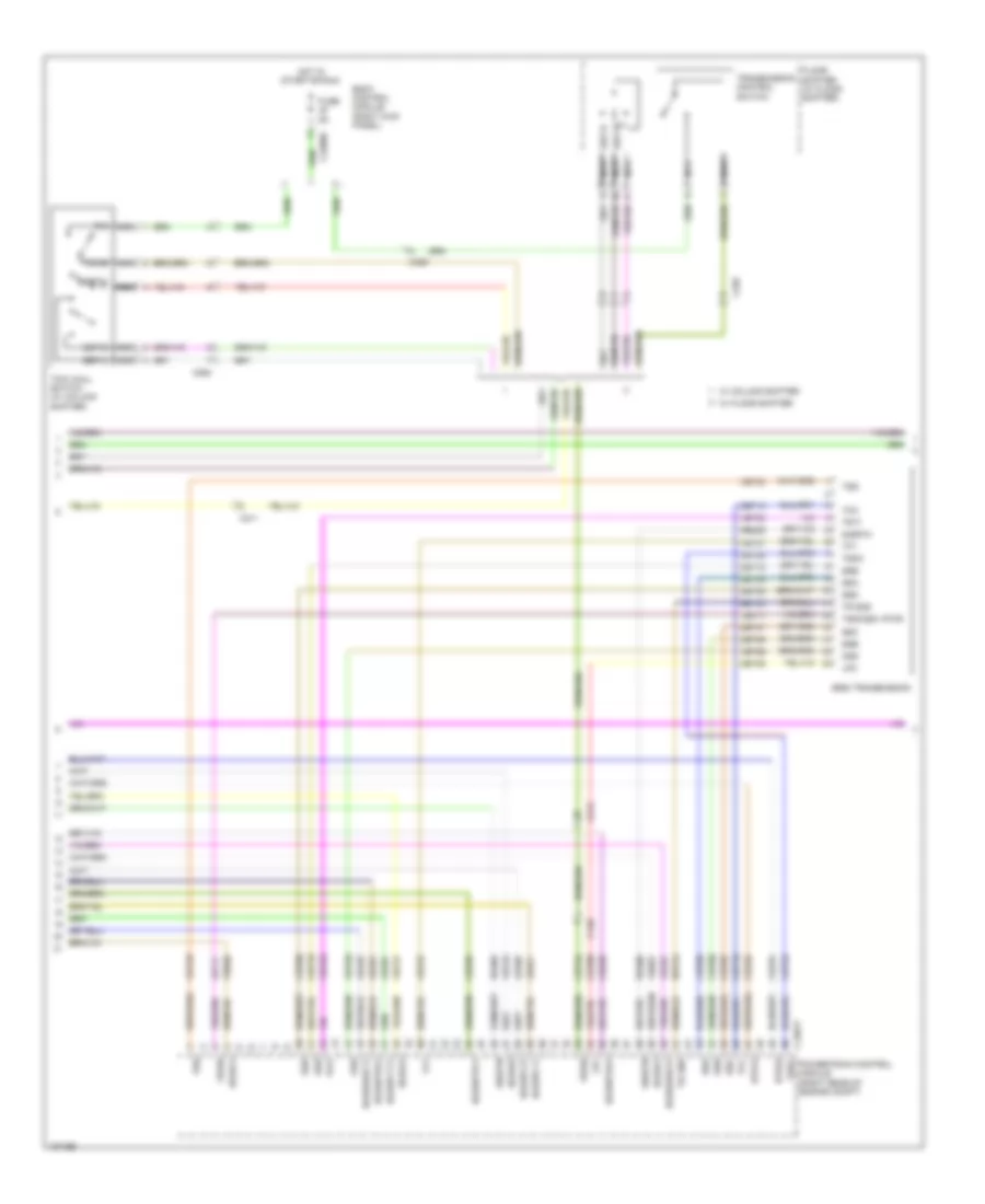
3.5L Turbo, Engine Performance Wiring Diagram (3 of 6) for Ford F-150 XL 2014
List of elements for 3.5L Turbo, Engine Performance Wiring Diagram (3 of 6) for Ford F-150 XL 2014:
- (w/ floor shifter) floor shifter
- Bcs2 alt
- Body control module (right kick panel)
- Bps
- C-vref
- C1551b
- C1551e
- C210
- C211
- C214
- C2280b
- C2280f
- C329
- Cbb75
- Ccb08
- Ce205
- Ce206
- Ce207
- Ce208
- Ce209
- Ce210
- Ce226
- Ce305
- Ce308
- Ce412
- Ce426
- Ces09
- Cet07
- Cet25
- Cet34
- Cet42
- Cet43
- Cop3e
- Cop6f
- Ftp
- Fuel pump (fet)
- Fuse 5a
- Fvr
- Fvrrtn
- G100 (right side of engine compt)
- Gd113
- Hot in start or run
- Iat
- Iat1
- Inj1
- Inj1rtn
- Inj2
- Inj2rtn
- Inj3
- Inj3rtn
- Inj4
- Inj4rtn
- Inj5
- Inj5rtn
- Inj6
- Inj6rtn
- Micro
- Nca
- Powertrain control module (pcm) (right rear of engine compt)
- Pwrgnd
- Re150
- Re205
- Re206
- Re207
- Re208
- Re209
- Re210
- Re226
- Re804
- S103
- Sigrtn
- Ssc
- Sst d
- Sst u
- Sst-d
- Sst-u
- Starting/ charging system
- Tacm+
- Tacm-
- Tcbp
- Tcip
- Ticp
- Tows
- Transmission control switch
- Tspc
- Turbocharger intake pressure & temperature (tcipt) sensor
- Vdc61
- Ve804
- Ve922
- Vpwr
- W/ column shifter
- W/ floor shifter
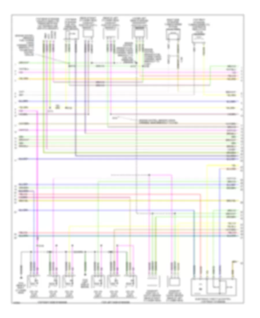
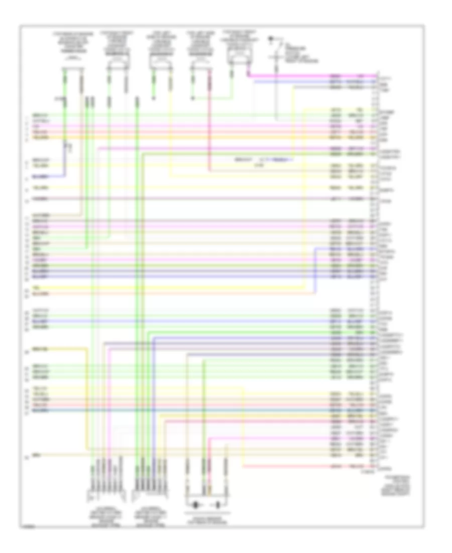
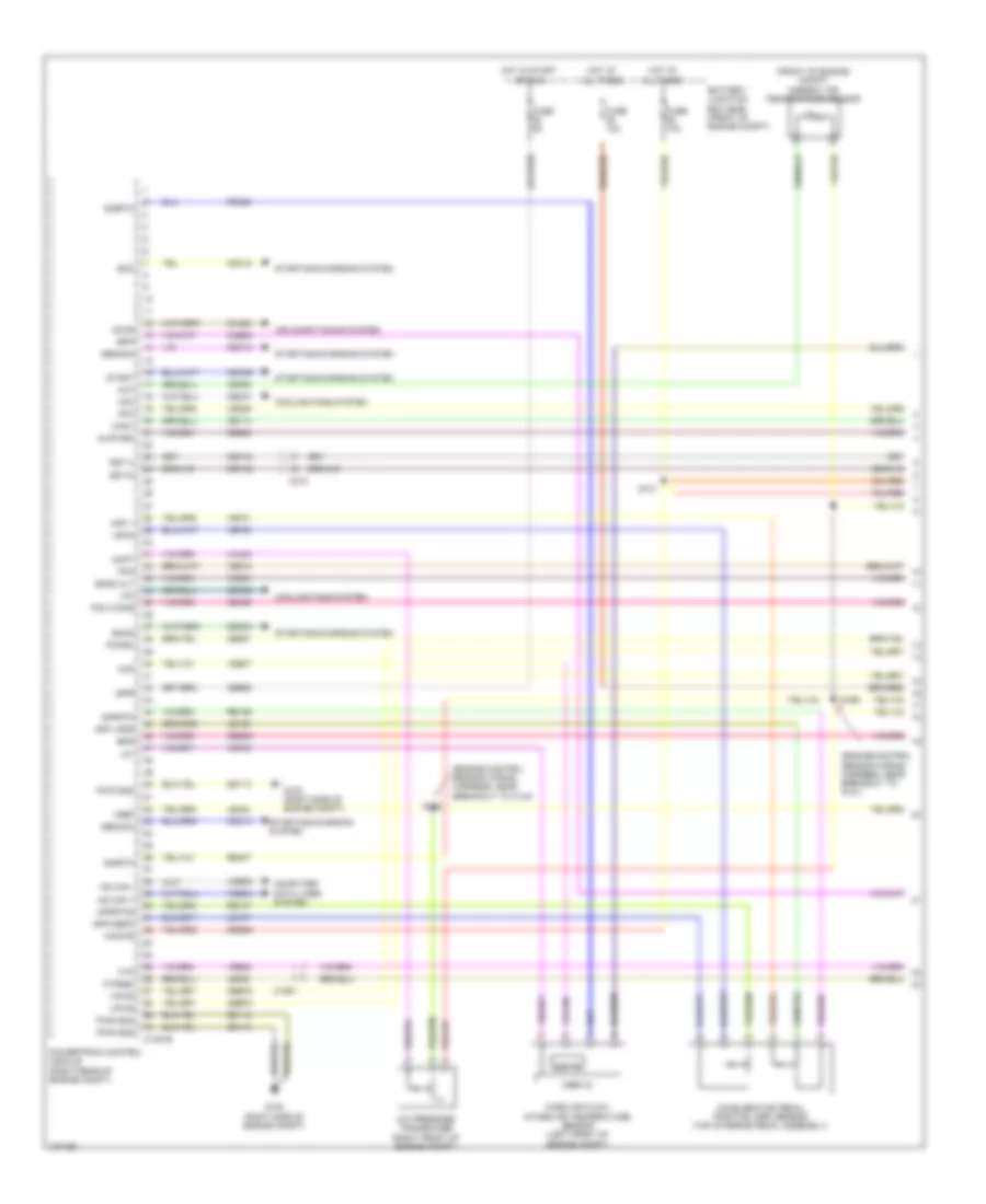
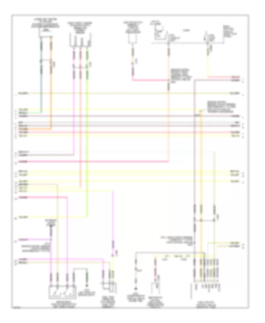
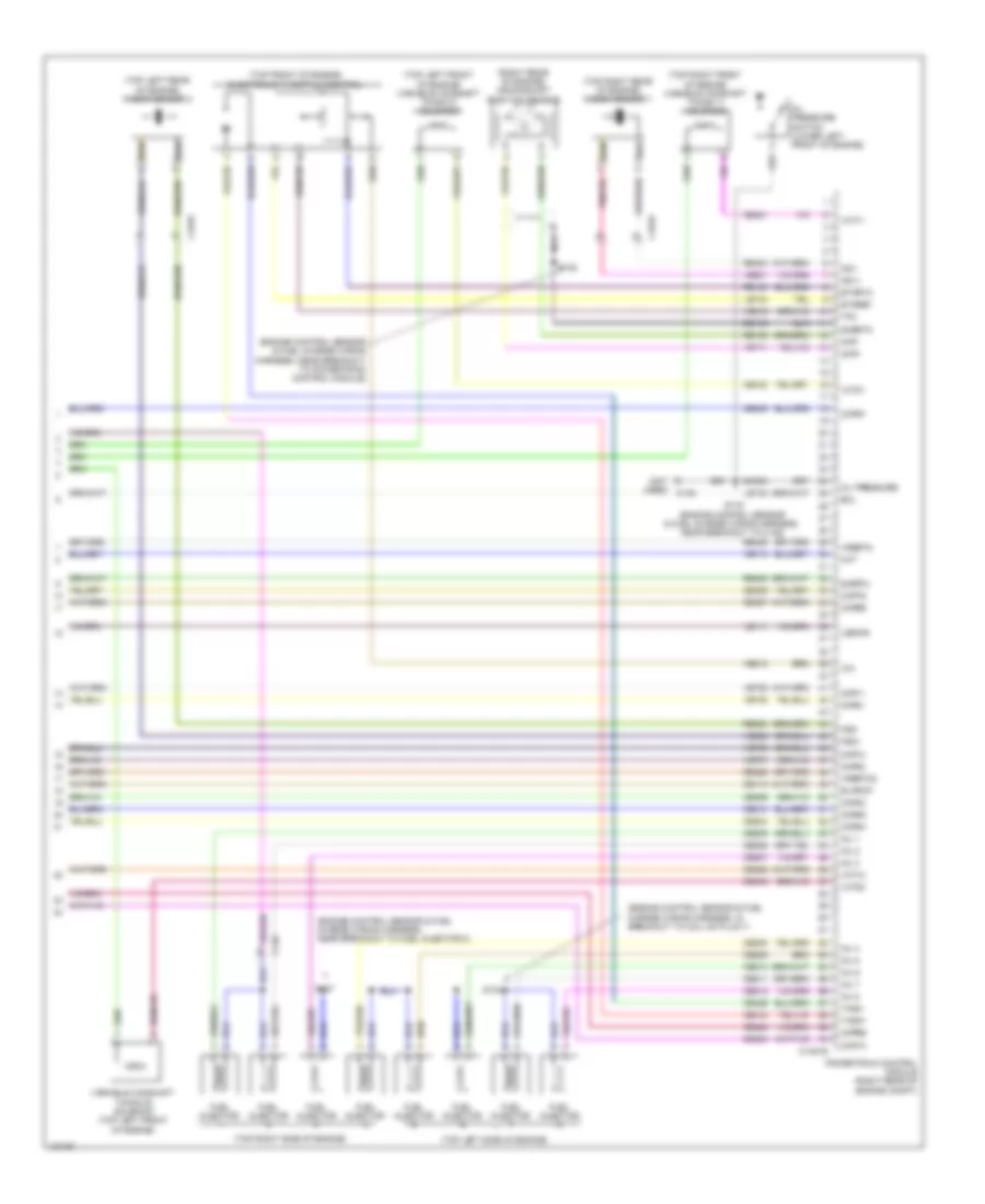
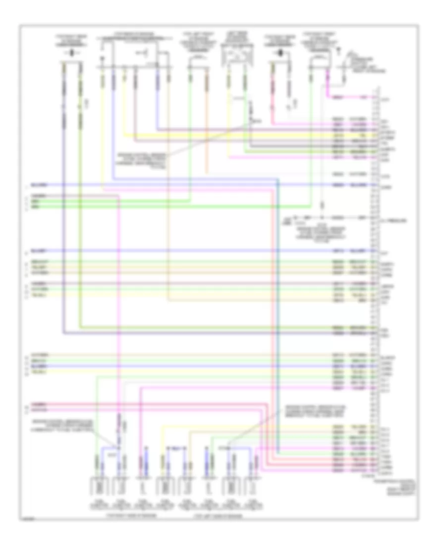
3.5L Turbo, Engine Performance Wiring Diagram (4 of 6) for Ford F-150 XL 2014
List of elements for 3.5L Turbo, Engine Performance Wiring Diagram (4 of 6) for Ford F-150 XL 2014:
- (rear of right cylinder head) cylinder head temperature (cht) sensor
- (top left side of engine)
- (top right side of engine)
- (under rear of vehicle, above spare tire) g401
- 6r80 transmission
- Battery junction box (bjb) (front of engine compt)
- C1581
- C1586
- C1587
- C210
- C310a
- Ce515
- Ce608
- Cet05
- Cet06
- Cet07
- Cet08
- Cet09
- Cet10
- Cet16
- Cet25
- Computer data lines system
- Cr167
- Ens
- Fp pwr
- Fp rtn
- Fpc
- Fpm
- Fuel injection pump (top left rear of engine)
- Fuel injector
- Fuel lvl1
- Fuel pump (fp) control module (near fuel tank)
- Fuel pump module (fuel tank assembly)
- Fuel pump relay
- Fuse 20a
- Gd117
- Gnd
- Hot at all times
- Hs can +
- Hs can -
- In breakout to fuel pump control module)
- Instrument panel cluster (ipc)
- Le111
- Lpc
- Nca
- Oss
- Re405
- Re515
- Restraints control module (rcm) (under center console)
- Ret04
- Ret24
- Ret33
- Rmc32
- Rtn
- S410
- Sigrtn
- Ssa
- Ssb
- Ssc
- Ssd
- Sse
- Tcc
- Tft
- Tr gnd
- Trp
- Tspc
- Tss
- Tss/oss vpwr
- Ve225
- Ve518
- Vet27
- Vet32
- Vmc11
- Vpwr
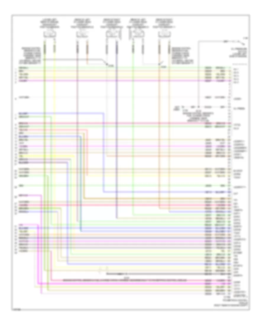
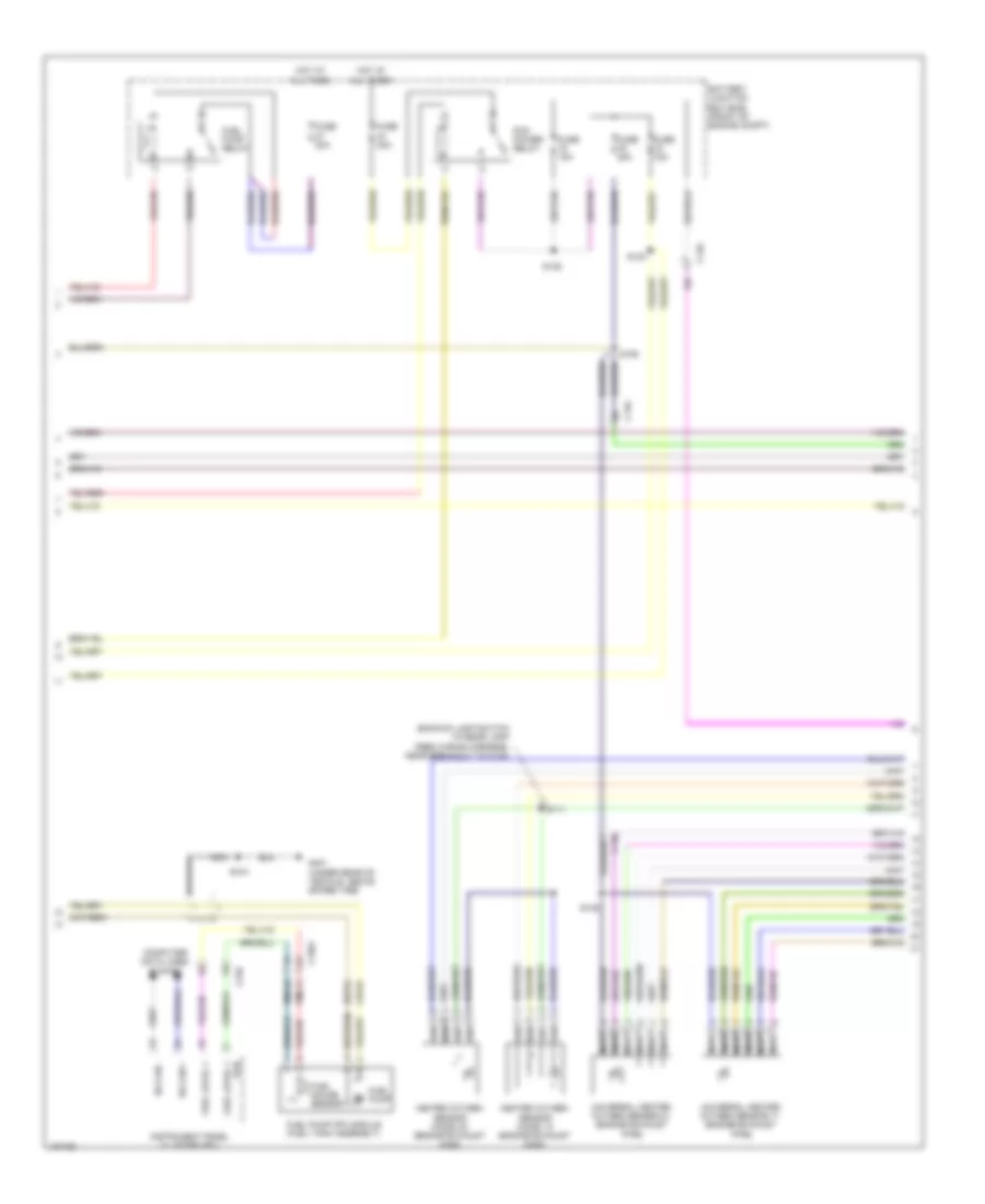
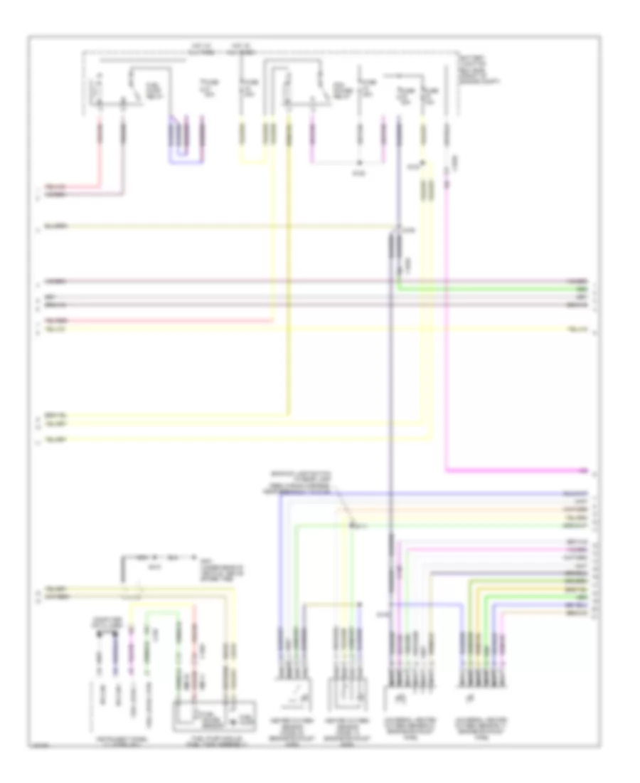
3.5L Turbo, Engine Performance Wiring Diagram (5 of 6) for Ford F-150 XL 2014
List of elements for 3.5L Turbo, Engine Performance Wiring Diagram (5 of 6) for Ford F-150 XL 2014:
- (engine control sensor & fuel charge wiring harness, near breakout to c1587) s166
- (engine control sensor & fuel charge wiring harness, near breakout to fuel rail pressure sensor)
- (engine control sensor & fuel charge wiring harness, near breakout to powertrain control module)
- (engine control sensor wiring harness, near breakout to c180)
- (lower left rear of engine) crankshaft position (ckp) sensor
- (rear of left cylinder head) camshaft position (cmp21) sensor 21
- (rear of right cylinder head) camshaft position (cmp11) sensor 11
- (right side of engine) turbocharger bypass valve (tcby)
- (top front of engine) turbocharger (tc) wastegate regulating valve solenoid
- (top left side of engine)
- (top rear of engine) fuel rail pressure (frp) sensor
- (top rear of engine) manifold absolute pressure/intake air temperature (map/iat2) sensor 2
- (top right side of engine)
- C136
- Camshaft position 12 (cmp12) sensor (rear of right cylinder head)
- Camshaft position 22 (cmp22) sensor (rear of left cylinder head)
- Coil on plug (cop) 1
- Coil on plug (cop) 2
- Coil on plug (cop) 3
- Coil on plug (cop) 4
- Coil on plug (cop) 5
- Coil on plug (cop) 6
- E-vref
- Electronic throttle control (top front of engine)
- G104 (rear of right cylinder head)
- G105 (left side of engine)
- Iat2
- S104
- S113
- S128
- S139
- S164
- S165
- S173
- S174
- Sigrtn
- Tmap
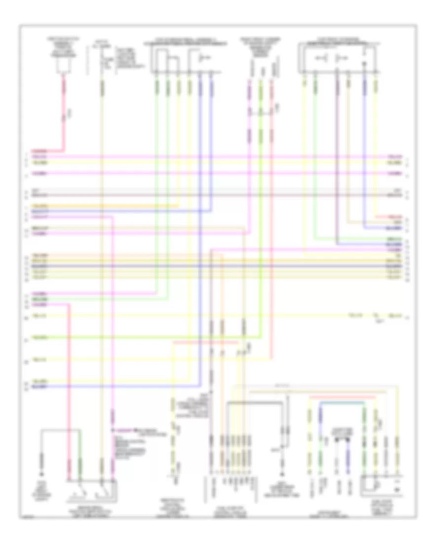
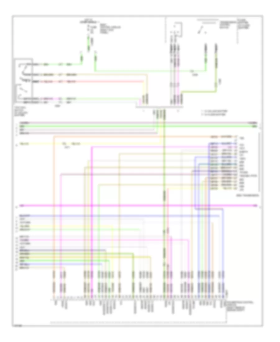
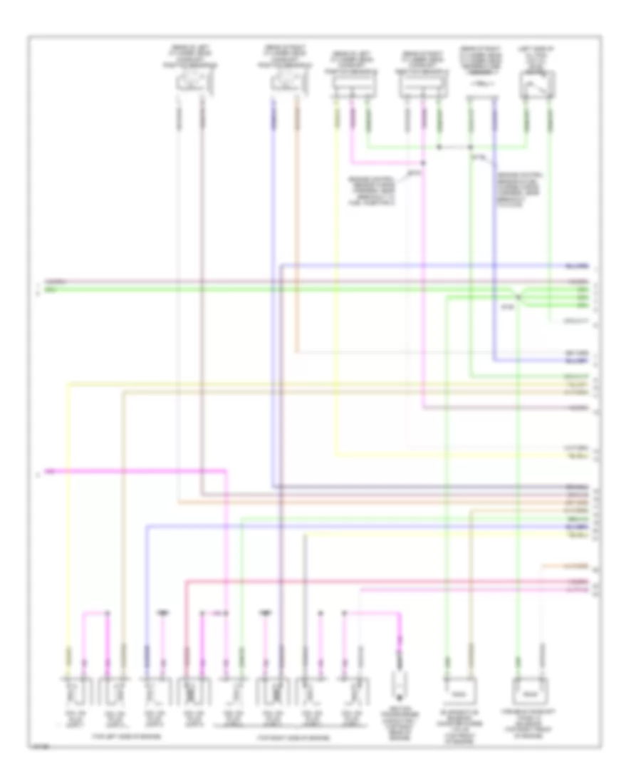
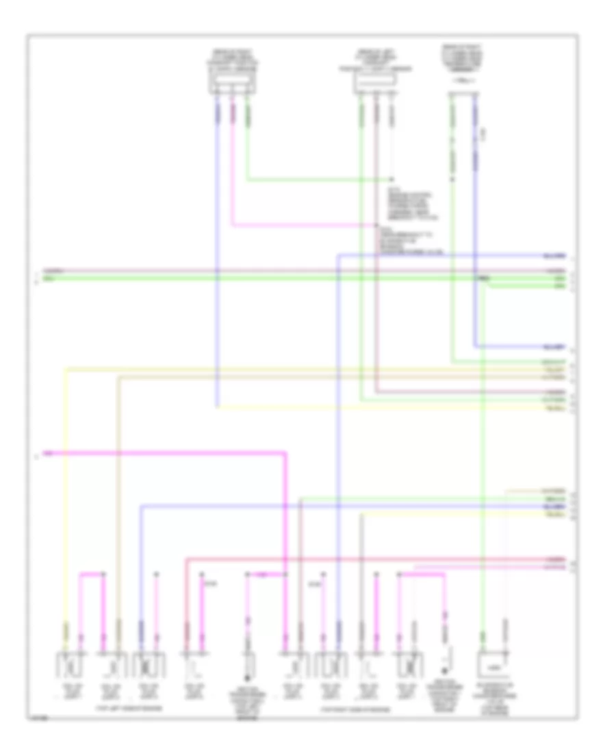
3.5L Turbo, Engine Performance Wiring Diagram (6 of 6) for Ford F-150 XL 2014
List of elements for 3.5L Turbo, Engine Performance Wiring Diagram (6 of 6) for Ford F-150 XL 2014:
- (top left side of engine) variable camshaft timing (vct21) solenoid 21
- (top left side of engine) variable camshaft timing (vct22) solenoid 22
- (top rear of engine) evaporative emission (evap) canister purge valve
- (top right front of engine) variable camshaft timing (vct11) solenoid 11
- (top right front of engine) variable camshaft timing (vct12) solenoid 12
- C146
- C1551e
- Ce235
- Ce236
- Ce303
- Ce304
- Ce306
- Ce307
- Ce421
- Ce422
- Ce435
- Ce442
- Ce443
- Cet05
- Cet06
- Cet08
- Cet09
- Cet10
- Cet16
- Cht
- Ckp
- Cmc24
- Cmp11
- Cmp12
- Cmp21
- Cmp22
- Cop1a
- Cop2c
- Cop4b
- Cop5d
- Etcref
- Etcrtn
- Frp
- Iat2
- Knock sensor (top rear of engine)
- Ks1 +
- Ks1 -
- Ks2 +
- Ks2 -
- Le111
- Le134
- Le143
- Le144
- Le423
- Le448
- Le449
- Le450
- Le451
- Le452
- Le453
- Lpc
- Map
- Nca
- Oil pressure switch (lower left front of engine)
- Ops
- Oss
- Powertrain control module (pcm) (right rear of engine compt)
- Re134
- Re323
- Re324
- Re405
- Re454
- Ret04
- Ret24
- Ret33
- Sigrtn
- Ssa
- Ssb
- Ssd
- Sse
- Tan
- Tcby
- Tcc
- Tcwrvs
- Tft
- Tp 1
- Tp 2
- Tr gnd
- Trp
- Tss
- Universal heated oxygen sensor (ho2s) 11 (engine exhaust pipe)
- Universal heated oxygen sensor (ho2s) 21 (engine exhaust pipe)
- Uo2s11
- Uo2s21
- Uo2sgref11
- Uo2sgref21
- Uo2shtr11
- Uo2shtr21
- Uo2spc11
- Uo2spc21
- Uo2spct21
- Uo2ssptc11
- Vct11
- Vct12
- Vct21
- Vct22
- Ve706
- Ve707
- Ve711
- Ve712
- Ve727
- Ve740
- Ve801
- Ve802
- Ve804
- Ve818
- Ve819
- Ve824
- Ve826
- Ve827
- Vet27
- Vet32
- Vpwr
- Vref
3.7L CNG
3.7L CNG, Engine Performance Wiring Diagram (1 of 6) for Ford F-150 XL 2014
List of elements for 3.7L CNG, Engine Performance Wiring Diagram (1 of 6) for Ford F-150 XL 2014:
- (engine control sensor wiring harness, near breakout to body control module) s240
- (engine control sensor wiring harness, near breakout to c144) s162
- (engine control sensor wiring harness, near breakout to g101) s169
- (under left center of vehicle) evaporative emission canister vent solenoid
- A/c pressure transducer (right front of engine compt)
- Aat
- Accr
- Acpt
- Air conditioning system
- Ambient air temperature sensor (front of engine compt)
- App1
- App2
- Apprtn1
- Apprtn2
- Appvref1
- Appvref2
- Battery junction box (bjb) (front of engine compt)
- Bcs2 alt
- Body control module (right kick panel)
- Bpp
- Bps
- C1581
- C175b
- C210
- C2280f
- Canv
- Cbb53
- Cbb75
- Ccb08
- Cdc10
- Cdc12
- Cdc15
- Cdc35
- Cdc54
- Ce114
- Ce436
- Ce607
- Ce608
- Cec01
- Cec02
- Ces09
- Cet42
- Cet43
- Ch302
- Computer data lines system
- Cooling fans system
- Digital
- Fpc
- Fpm
- Ftp
- Ftpref
- Fuel pump (fet)
- Fuel tank pressure (ftp) sensor (fuel tank assembly)
- Fuse 10a
- Fuse 5a
- G100 (right side of engine compt)
- Gd113
- Gencom
- Genmon
- Hfc
- Hot at all times
- Hot in run or start
- Hs can +
- Hs can -
- Iat
- Injpwrm
- Ispr
- Kapwr
- Le136
- Le137
- Le230
- Le424
- Lfc
- Maf
- Mass air flow/intake air temperature sensor (left front of engine compt)
- Micro
- Pcm wake
- Pcm wake up (fet)
- Pcmrc
- Powertrain control module (right rear of engine compt)
- Pwrgnd
- Re136
- Re137
- Re320
- Re407
- S101
- Sbb26
- Sigrtn
- Smc
- Smcs
- Sst d
- Sst u
- Start
- Starting/charging system
- Vdb04
- Vdb05
- Vdc61
- Ve225
- Ve518
- Ve701
- Ve702
- Ve740
- Ve750
- Ve807
- Ve922
- Vh433
- Vpwr
- Vref
3.7L CNG, Engine Performance Wiring Diagram (2 of 6) for Ford F-150 XL 2014
List of elements for 3.7L CNG, Engine Performance Wiring Diagram (2 of 6) for Ford F-150 XL 2014:
- (ignition switch assembly) passive anti-theft transceiver
- (right front corner of engine compt) generator current sensor
- (top front of engine) electronic throttle control
- (top of brake pedal assembly) accelerator pedal position (app) sensor
- 1 rtn
- Battery junction box (bjb) (front of engine compt)
- Bcs2 alt
- Brake pedal position (bpp) switch (left side of dash)
- C1581
- C192
- C210
- C211
- C214
- C310a
- Ce515
- Ce608
- Computer data lines system
- Cr167
- Ens
- Exterior lights system
- Fp pwr
- Fp rtn
- Fpc
- Fpm
- Fuel lvl
- Fuel lvl 1
- Fuel pump (fp) control module (near fuel tank)
- Fuel pump (fp) module (fuel tank assembly)
- Fuse 10a
- G102 (left front of engine compt)
- G401 (under rear of vehicle, above spare tire)
- Gd117
- Gnd
- Hot at all times
- Hs can +
- Hs can -
- Instrument panel cluster (ipc)
- Nca
- Re515
- Restraints control module (rcm) (under center console)
- Rmc32
- S112 (engine control sensor wiring harness, near breakout to c110)
- S407 (tail lamps wiring harness, in breakout to fuel pump control module)
- S410
- Sigrtn
- Ve225
- Ve518
- Vmc11
- Vpwr fuel
- Vref
3.7L CNG, Engine Performance Wiring Diagram (3 of 6) for Ford F-150 XL 2014
List of elements for 3.7L CNG, Engine Performance Wiring Diagram (3 of 6) for Ford F-150 XL 2014:
- (engine control sensor wiring harness, near breakout to mass air flow/intake air temperature sensor)
- Battery junction box (bjb) (front of engine compt)
- C140
- C146
- C175t
- C214
- Ce233
- Ce234
- Cet05
- Cet06
- Cet07
- Cet08
- Cet09
- Cet10
- Cet18
- Cet25
- Cet34
- Fuel pump relay
- Fuse 15a
- Fuse 20a
- Fuse 40a
- Ho2s12
- Ho2s22
- Hot at all times
- Htr12
- Htr22
- Le111
- Lpc
- Oss
- Pcm power relay
- Powertrain control module (right rear of engine compt)
- Re405
- Ret24
- S103
- S107
- S125
- S129
- Sigrtn
- Ssa
- Ssb
- Ssc
- Ssd
- Sse
- Tcc
- Tft
- Tows
- Tr p
- Trgnd
- Tspc
- Tss
- Ve731
- Ve733
- Vet26
- Vet27
- Vet32
- Vet33
- Vpwr
- W/ column shifter
- W/ floor shifter
3.7L CNG, Engine Performance Wiring Diagram (4 of 6) for Ford F-150 XL 2014
List of elements for 3.7L CNG, Engine Performance Wiring Diagram (4 of 6) for Ford F-150 XL 2014:
- (rear of right cylinder head) cylinder head temperature sensor
- (w/ column shifter)
- (w/ floor shifter) floor shifter
- 6r80 transmission
- Body control module (right kick panel)
- C1026
- C2280b
- C264
- C329
- Cet05
- Cet06
- Cet07
- Cet08
- Cet09
- Cet10
- Cet18
- Cet25
- Fuse 5a
- Heated oxygen sensor (ho2s) 12
- Heated oxygen sensor (ho2s) 22
- Hot in start or run
- Le111
- Lpc
- Nca
- Oss
- R/s
- Re405
- Ret24
- S111 (backup lamp switch to rear lamp feed wiring harness, near breakout to c140)
- S148
- Sigrtn
- Ssa
- Ssb
- Ssc
- Ssd
- Sse
- Sst d
- Sst u
- Sst-d
- Sst-u
- Tcc
- Tft
- Tow haul switch
- Tows
- Tr gnd
- Tr p
- Transmission control switch
- Tspc
- Tss
- Tss/oss vpwr
- Universal heated oxygen sensor 11 (engine exhaust pipe)
- Universal heated oxygen sensor 21 (engine exhaust pipe)
- Vet26
- Vet27
- Vet32
- Vet33
- W/ column shifter
- W/ floor shifter
3.7L CNG, Engine Performance Wiring Diagram (5 of 6) for Ford F-150 XL 2014
List of elements for 3.7L CNG, Engine Performance Wiring Diagram (5 of 6) for Ford F-150 XL 2014:
- (engine control sensor & fuel charge wiring harness, near breakout to camshaft position 21 sensor)
- (top left rear of engine) knock sensor
- (top left side of engine)
- (top left side of engine) variable camshaft timing solenoid 21
- (top left side of engine) variable camshaft timing solenoid 22
- (top right front of engine) variable camshaft timing solenoid 11
- (top right front of engine) variable camshaft timing solenoid 12
- (top right rear of engine) evaporative emission canister purge valve
- (top right side of engine)
- C146
- Coil on plug
- Fuel injector
- Fuel injector (top left side of engine)
- Fuel injector (top right side of engine)
- S135
- S136
- S137
- S139
- Tan
3.7L CNG, Engine Performance Wiring Diagram (6 of 6) for Ford F-150 XL 2014
List of elements for 3.7L CNG, Engine Performance Wiring Diagram (6 of 6) for Ford F-150 XL 2014:
- (engine control sensor & fuel charge wiring harness, near breakout to powertrain control module)
- (engine control sensor & fuel charge wiring harness, near breakout to universal heated oxygen sensor 11)
- (lower left rear of engine) crankshaft position sensor
- (not used)
- (rear of left cylinder head) camshaft position sensor 21
- (rear of left cylinder head) camshaft position sensor 22
- (rear of right cylinder head) camshaft position sensor 11
- (rear of right cylinder head) camshaft position sensor 12
- C146
- C175e
- Ce113
- Ce205
- Ce206
- Ce207
- Ce208
- Ce209
- Ce210
- Ce235
- Ce236
- Ce303
- Ce304
- Ce305
- Ce306
- Ce307
- Ce308
- Ce412
- Ce421
- Ce422
- Ce426
- Ce442
- Ce443
- Cht
- Ckp+
- Ckp-
- Cmc24
- Cmp11
- Cmp12
- Cmp21
- Cmp22
- Cop1a
- Cop2c
- Cop3e
- Cop4b
- Cop5d
- Cop6f
- De135
- Etcref
- Etcrtn
- Evapcp
- Inj 1
- Inj 2
- Inj 3
- Inj 4
- Inj 5
- Inj 6
- Ks1+
- Ks1-
- Ks2+
- Ks2-
- Le134
- Le448
- Le449
- Le450
- Le451
- Le452
- Le453
- Nca
- Oil press
- Oil pressure switch (lower left side of engine)
- Powertrain control module (right rear of engine compt)
- Re134
- Re135
- Re323
- Re324
- Re405
- Re429
- S116 (engine control sensor & fuel charge wiring harness, near breakout to c146)
- S138
- S159
- S160
- Shdrtn
- Sigrtn
- Tacm+
- Tacm-
- Tp1
- Tp2
- Uo2s11
- Uo2s21
- Uo2sgref11
- Uo2sgref21
- Uo2shtr11
- Uo2shtr21
- Uo2spc11
- Uo2spc21
- Uo2spct11
- Uo2spct21
- Vct11
- Vct12
- Vct21
- Vct22
- Ve706
- Ve707
- Ve711
- Ve712
- Ve801
- Ve802
- Ve818
- Ve819
- Ve826
- Ve827
- Vrsrtn
- Vrsrtn2
3.7L FLEX FUEL
3.7L Flex Fuel, Engine Performance Wiring Diagram (1 of 6) for Ford F-150 XL 2014
List of elements for 3.7L Flex Fuel, Engine Performance Wiring Diagram (1 of 6) for Ford F-150 XL 2014:
- (engine control sensor wiring harness, near breakout to body control module) s240
- (engine control sensor wiring harness, near breakout to c144) s162
- (engine control sensor wiring harness, near breakout to g101) s169
- (under left center of vehicle) evaporative emission canister vent solenoid
- A/c pressure transducer (right front of engine compt)
- Aat
- Accr
- Acpt
- Air conditioning system
- Ambient air temperature sensor (front of engine compt)
- App1
- App2
- Apprtn1
- Apprtn2
- Appvref1
- Appvref2
- Battery junction box (bjb) (front of engine compt)
- Bcs2 alt
- Body control module (right kick panel)
- Bpp
- Bps
- C1581
- C175b
- C210
- C2280f
- Canv
- Cbb53
- Cbb75
- Ccb08
- Cdc10
- Cdc12
- Cdc15
- Cdc35
- Cdc54
- Ce114
- Ce436
- Ce607
- Ce608
- Cec01
- Cec02
- Ces09
- Cet42
- Cet43
- Ch302
- Computer data lines system
- Cooling fans system
- Digital
- Fpc
- Fpm
- Ftp
- Ftpref
- Fuel pump (fet)
- Fuel tank pressure (ftp) sensor (fuel tank assembly)
- Fuse 10a
- Fuse 5a
- G100 (right side of engine compt)
- Gd113
- Gencom
- Genmon
- Hfc
- Hot at all times
- Hot in run or start
- Hs can +
- Hs can -
- Iat
- Injpwrm
- Ispr
- Kapwr
- Le136
- Le137
- Le230
- Le424
- Lfc
- Maf
- Mass air flow/intake air temperature sensor (left front of engine compt)
- Micro
- Pcm wake
- Pcm wake up (fet)
- Pcmrc
- Powertrain control module (right rear of engine compt)
- Pwrgnd
- Re136
- Re137
- Re320
- Re407
- S101
- Sbb26
- Sigrtn
- Smc
- Smcs
- Sst d
- Sst u
- Start
- Starting/charging system
- Vdb04
- Vdb05
- Vdc61
- Ve225
- Ve518
- Ve701
- Ve702
- Ve740
- Ve750
- Ve807
- Ve922
- Vh433
- Vpwr
- Vref
3.7L Flex Fuel, Engine Performance Wiring Diagram (2 of 6) for Ford F-150 XL 2014
List of elements for 3.7L Flex Fuel, Engine Performance Wiring Diagram (2 of 6) for Ford F-150 XL 2014:
- (ignition switch assembly) passive anti-theft transceiver
- (right front corner of engine compt) generator current sensor
- (top front of engine) electronic throttle control
- (top of brake pedal assembly) accelerator pedal position (app) sensor
- 1 rtn
- Battery junction box (bjb) (front of engine compt)
- Bcs2 alt
- Brake pedal position (bpp) switch (left side of dash)
- C1581
- C192
- C210
- C211
- C214
- C310a
- Ce515
- Ce608
- Computer data lines system
- Cr167
- Ens
- Exterior lights system
- Fp pwr
- Fp rtn
- Fpc
- Fpm
- Fuel lvl
- Fuel lvl 1
- Fuel pump (fp) control module (near fuel tank)
- Fuel pump (fp) module (fuel tank assembly)
- Fuse 10a
- G102 (left front of engine compt)
- G401 (under rear of vehicle, above spare tire)
- Gd117
- Gnd
- Hot at all times
- Hs can +
- Hs can -
- Instrument panel cluster (ipc)
- Nca
- Re515
- Restraints control module (rcm) (under center console)
- Rmc32
- S112 (engine control sensor wiring harness, near breakout to c110)
- S407 (tail lamps wiring harness, in breakout to fuel pump control module)
- S410
- Sigrtn
- Ve225
- Ve518
- Vmc11
- Vpwr fuel
- Vref
3.7L Flex Fuel, Engine Performance Wiring Diagram (3 of 6) for Ford F-150 XL 2014
List of elements for 3.7L Flex Fuel, Engine Performance Wiring Diagram (3 of 6) for Ford F-150 XL 2014:
- (engine control sensor wiring harness, near breakout to mass air flow/intake air temperature sensor)
- Battery junction box (bjb) (front of engine compt)
- C140
- C146
- C175t
- C214
- Ce233
- Ce234
- Cet05
- Cet06
- Cet07
- Cet08
- Cet09
- Cet10
- Cet18
- Cet25
- Cet34
- Fuel pump relay
- Fuse 15a
- Fuse 20a
- Fuse 40a
- Ho2s12
- Ho2s22
- Hot at all times
- Htr12
- Htr22
- Le111
- Lpc
- Oss
- Pcm power relay
- Powertrain control module (right rear of engine compt)
- Re405
- Ret24
- S103
- S107
- S125
- S129
- Sigrtn
- Ssa
- Ssb
- Ssc
- Ssd
- Sse
- Tcc
- Tft
- Tows
- Tr p
- Trgnd
- Tspc
- Tss
- Ve731
- Ve733
- Vet26
- Vet27
- Vet32
- Vet33
- Vpwr
- W/ column shifter
- W/ floor shifter
3.7L Flex Fuel, Engine Performance Wiring Diagram (4 of 6) for Ford F-150 XL 2014
List of elements for 3.7L Flex Fuel, Engine Performance Wiring Diagram (4 of 6) for Ford F-150 XL 2014:
- (rear of right cylinder head) cylinder head temperature sensor
- (w/ column shifter)
- (w/ floor shifter) floor shifter
- 6r80 transmission
- Body control module (right kick panel)
- C1026
- C2280b
- C264
- C329
- Cet05
- Cet06
- Cet07
- Cet08
- Cet09
- Cet10
- Cet18
- Cet25
- Fuse 5a
- Heated oxygen sensor (ho2s) 12
- Heated oxygen sensor (ho2s) 22
- Hot in start or run
- Le111
- Lpc
- Nca
- Oss
- R/s
- Re405
- Ret24
- S111 (backup lamp switch to rear lamp feed wiring harness, near breakout to c140)
- S148
- Sigrtn
- Ssa
- Ssb
- Ssc
- Ssd
- Sse
- Sst d
- Sst u
- Sst-d
- Sst-u
- Tcc
- Tft
- Tow haul switch
- Tows
- Tr gnd
- Tr p
- Transmission control switch
- Tspc
- Tss
- Tss/oss vpwr
- Universal heated oxygen sensor 11 (engine exhaust pipe)
- Universal heated oxygen sensor 21 (engine exhaust pipe)
- Vet26
- Vet27
- Vet32
- Vet33
- W/ column shifter
- W/ floor shifter
3.7L Flex Fuel, Engine Performance Wiring Diagram (5 of 6) for Ford F-150 XL 2014
List of elements for 3.7L Flex Fuel, Engine Performance Wiring Diagram (5 of 6) for Ford F-150 XL 2014:
- (engine control sensor & fuel charge wiring harness, near breakout to camshaft position 21 sensor)
- (top left rear of engine) knock sensor
- (top left side of engine)
- (top left side of engine) variable camshaft timing solenoid 21
- (top left side of engine) variable camshaft timing solenoid 22
- (top right front of engine) variable camshaft timing solenoid 11
- (top right front of engine) variable camshaft timing solenoid 12
- (top right rear of engine) evaporative emission canister purge valve
- (top right side of engine)
- C146
- Coil on plug
- Fuel injector
- Fuel injector (top left side of engine)
- Fuel injector (top right side of engine)
- S135
- S136
- S137
- S139
- Tan
3.7L Flex Fuel, Engine Performance Wiring Diagram (6 of 6) for Ford F-150 XL 2014
List of elements for 3.7L Flex Fuel, Engine Performance Wiring Diagram (6 of 6) for Ford F-150 XL 2014:
- (engine control sensor & fuel charge wiring harness, near breakout to powertrain control module)
- (engine control sensor & fuel charge wiring harness, near breakout to universal heated oxygen sensor 11)
- (lower left rear of engine) crankshaft position sensor
- (not used)
- (rear of left cylinder head) camshaft position sensor 21
- (rear of left cylinder head) camshaft position sensor 22
- (rear of right cylinder head) camshaft position sensor 11
- (rear of right cylinder head) camshaft position sensor 12
- C146
- C175e
- Ce113
- Ce205
- Ce206
- Ce207
- Ce208
- Ce209
- Ce210
- Ce235
- Ce236
- Ce303
- Ce304
- Ce305
- Ce306
- Ce307
- Ce308
- Ce412
- Ce421
- Ce422
- Ce426
- Ce442
- Ce443
- Cht
- Ckp+
- Ckp-
- Cmc24
- Cmp11
- Cmp12
- Cmp21
- Cmp22
- Cop1a
- Cop2c
- Cop3e
- Cop4b
- Cop5d
- Cop6f
- De135
- Etcref
- Etcrtn
- Evapcp
- Inj 1
- Inj 2
- Inj 3
- Inj 4
- Inj 5
- Inj 6
- Ks1+
- Ks1-
- Ks2+
- Ks2-
- Le134
- Le448
- Le449
- Le450
- Le451
- Le452
- Le453
- Nca
- Oil press
- Oil pressure switch (lower left side of engine)
- Powertrain control module (right rear of engine compt)
- Re134
- Re135
- Re323
- Re324
- Re405
- Re429
- S116 (engine control sensor & fuel charge wiring harness, near breakout to c146)
- S138
- S159
- S160
- Shdrtn
- Sigrtn
- Tacm+
- Tacm-
- Tp1
- Tp2
- Uo2s11
- Uo2s21
- Uo2sgref11
- Uo2sgref21
- Uo2shtr11
- Uo2shtr21
- Uo2spc11
- Uo2spc21
- Uo2spct11
- Uo2spct21
- Vct11
- Vct12
- Vct21
- Vct22
- Ve706
- Ve707
- Ve711
- Ve712
- Ve801
- Ve802
- Ve818
- Ve819
- Ve826
- Ve827
- Vrsrtn
- Vrsrtn2
3.7L LPG
3.7L LPG, Engine Performance Wiring Diagram (1 of 6) for Ford F-150 XL 2014
List of elements for 3.7L LPG, Engine Performance Wiring Diagram (1 of 6) for Ford F-150 XL 2014:
- (engine control sensor wiring harness, near breakout to body control module) s240
- (engine control sensor wiring harness, near breakout to c144) s162
- (engine control sensor wiring harness, near breakout to g101) s169
- (under left center of vehicle) evaporative emission canister vent solenoid
- A/c pressure transducer (right front of engine compt)
- Aat
- Accr
- Acpt
- Air conditioning system
- Ambient air temperature sensor (front of engine compt)
- App1
- App2
- Apprtn1
- Apprtn2
- Appvref1
- Appvref2
- Battery junction box (bjb) (front of engine compt)
- Bcs2 alt
- Body control module (right kick panel)
- Bpp
- Bps
- C1581
- C175b
- C210
- C2280f
- Canv
- Cbb53
- Cbb75
- Ccb08
- Cdc10
- Cdc12
- Cdc15
- Cdc35
- Cdc54
- Ce114
- Ce436
- Ce607
- Ce608
- Cec01
- Cec02
- Ces09
- Cet42
- Cet43
- Ch302
- Computer data lines system
- Cooling fans system
- Digital
- Fpc
- Fpm
- Ftp
- Ftpref
- Fuel pump (fet)
- Fuel tank pressure (ftp) sensor (fuel tank assembly)
- Fuse 10a
- Fuse 5a
- G100 (right side of engine compt)
- Gd113
- Gencom
- Genmon
- Hfc
- Hot at all times
- Hot in run or start
- Hs can +
- Hs can -
- Iat
- Injpwrm
- Ispr
- Kapwr
- Le136
- Le137
- Le230
- Le424
- Lfc
- Maf
- Mass air flow/intake air temperature sensor (left front of engine compt)
- Micro
- Pcm wake
- Pcm wake up (fet)
- Pcmrc
- Powertrain control module (right rear of engine compt)
- Pwrgnd
- Re136
- Re137
- Re320
- Re407
- S101
- Sbb26
- Sigrtn
- Smc
- Smcs
- Sst d
- Sst u
- Start
- Starting/charging system
- Vdb04
- Vdb05
- Vdc61
- Ve225
- Ve518
- Ve701
- Ve702
- Ve740
- Ve750
- Ve807
- Ve922
- Vh433
- Vpwr
- Vref
3.7L LPG, Engine Performance Wiring Diagram (2 of 6) for Ford F-150 XL 2014
List of elements for 3.7L LPG, Engine Performance Wiring Diagram (2 of 6) for Ford F-150 XL 2014:
- (ignition switch assembly) passive anti-theft transceiver
- (right front corner of engine compt) generator current sensor
- (top front of engine) electronic throttle control
- (top of brake pedal assembly) accelerator pedal position (app) sensor
- 1 rtn
- Battery junction box (bjb) (front of engine compt)
- Bcs2 alt
- Brake pedal position (bpp) switch (left side of dash)
- C1581
- C192
- C210
- C211
- C214
- C310a
- Ce515
- Ce608
- Computer data lines system
- Cr167
- Ens
- Exterior lights system
- Fp pwr
- Fp rtn
- Fpc
- Fpm
- Fuel lvl
- Fuel lvl 1
- Fuel pump (fp) control module (near fuel tank)
- Fuel pump (fp) module (fuel tank assembly)
- Fuse 10a
- G102 (left front of engine compt)
- G401 (under rear of vehicle, above spare tire)
- Gd117
- Gnd
- Hot at all times
- Hs can +
- Hs can -
- Instrument panel cluster (ipc)
- Nca
- Re515
- Restraints control module (rcm) (under center console)
- Rmc32
- S112 (engine control sensor wiring harness, near breakout to c110)
- S407 (tail lamps wiring harness, in breakout to fuel pump control module)
- S410
- Sigrtn
- Ve225
- Ve518
- Vmc11
- Vpwr fuel
- Vref
3.7L LPG, Engine Performance Wiring Diagram (3 of 6) for Ford F-150 XL 2014
List of elements for 3.7L LPG, Engine Performance Wiring Diagram (3 of 6) for Ford F-150 XL 2014:
- (engine control sensor wiring harness, near breakout to mass air flow/intake air temperature sensor)
- Battery junction box (bjb) (front of engine compt)
- C140
- C146
- C175t
- C214
- Ce233
- Ce234
- Cet05
- Cet06
- Cet07
- Cet08
- Cet09
- Cet10
- Cet18
- Cet25
- Cet34
- Fuel pump relay
- Fuse 15a
- Fuse 20a
- Fuse 40a
- Ho2s12
- Ho2s22
- Hot at all times
- Htr12
- Htr22
- Le111
- Lpc
- Oss
- Pcm power relay
- Powertrain control module (right rear of engine compt)
- Re405
- Ret24
- S103
- S107
- S125
- S129
- Sigrtn
- Ssa
- Ssb
- Ssc
- Ssd
- Sse
- Tcc
- Tft
- Tows
- Tr p
- Trgnd
- Tspc
- Tss
- Ve731
- Ve733
- Vet26
- Vet27
- Vet32
- Vet33
- Vpwr
- W/ column shifter
- W/ floor shifter
3.7L LPG, Engine Performance Wiring Diagram (4 of 6) for Ford F-150 XL 2014
List of elements for 3.7L LPG, Engine Performance Wiring Diagram (4 of 6) for Ford F-150 XL 2014:
- (rear of right cylinder head) cylinder head temperature sensor
- (w/ column shifter)
- (w/ floor shifter) floor shifter
- 6r80 transmission
- Body control module (right kick panel)
- C1026
- C2280b
- C264
- C329
- Cet05
- Cet06
- Cet07
- Cet08
- Cet09
- Cet10
- Cet18
- Cet25
- Fuse 5a
- Heated oxygen sensor (ho2s) 12
- Heated oxygen sensor (ho2s) 22
- Hot in start or run
- Le111
- Lpc
- Nca
- Oss
- R/s
- Re405
- Ret24
- S111 (backup lamp switch to rear lamp feed wiring harness, near breakout to c140)
- S148
- Sigrtn
- Ssa
- Ssb
- Ssc
- Ssd
- Sse
- Sst d
- Sst u
- Sst-d
- Sst-u
- Tcc
- Tft
- Tow haul switch
- Tows
- Tr gnd
- Tr p
- Transmission control switch
- Tspc
- Tss
- Tss/oss vpwr
- Universal heated oxygen sensor 11 (engine exhaust pipe)
- Universal heated oxygen sensor 21 (engine exhaust pipe)
- Vet26
- Vet27
- Vet32
- Vet33
- W/ column shifter
- W/ floor shifter
3.7L LPG, Engine Performance Wiring Diagram (5 of 6) for Ford F-150 XL 2014
List of elements for 3.7L LPG, Engine Performance Wiring Diagram (5 of 6) for Ford F-150 XL 2014:
- (engine control sensor & fuel charge wiring harness, near breakout to camshaft position 21 sensor)
- (top left rear of engine) knock sensor
- (top left side of engine)
- (top left side of engine) variable camshaft timing solenoid 21
- (top left side of engine) variable camshaft timing solenoid 22
- (top right front of engine) variable camshaft timing solenoid 11
- (top right front of engine) variable camshaft timing solenoid 12
- (top right rear of engine) evaporative emission canister purge valve
- (top right side of engine)
- C146
- Coil on plug
- Fuel injector
- Fuel injector (top left side of engine)
- Fuel injector (top right side of engine)
- S135
- S136
- S137
- S139
- Tan
3.7L LPG, Engine Performance Wiring Diagram (6 of 6) for Ford F-150 XL 2014
List of elements for 3.7L LPG, Engine Performance Wiring Diagram (6 of 6) for Ford F-150 XL 2014:
- (engine control sensor & fuel charge wiring harness, near breakout to powertrain control module)
- (engine control sensor & fuel charge wiring harness, near breakout to universal heated oxygen sensor 11)
- (lower left rear of engine) crankshaft position sensor
- (not used)
- (rear of left cylinder head) camshaft position sensor 21
- (rear of left cylinder head) camshaft position sensor 22
- (rear of right cylinder head) camshaft position sensor 11
- (rear of right cylinder head) camshaft position sensor 12
- C146
- C175e
- Ce113
- Ce205
- Ce206
- Ce207
- Ce208
- Ce209
- Ce210
- Ce235
- Ce236
- Ce303
- Ce304
- Ce305
- Ce306
- Ce307
- Ce308
- Ce412
- Ce421
- Ce422
- Ce426
- Ce442
- Ce443
- Cht
- Ckp+
- Ckp-
- Cmc24
- Cmp11
- Cmp12
- Cmp21
- Cmp22
- Cop1a
- Cop2c
- Cop3e
- Cop4b
- Cop5d
- Cop6f
- De135
- Etcref
- Etcrtn
- Evapcp
- Inj 1
- Inj 2
- Inj 3
- Inj 4
- Inj 5
- Inj 6
- Ks1+
- Ks1-
- Ks2+
- Ks2-
- Le134
- Le448
- Le449
- Le450
- Le451
- Le452
- Le453
- Nca
- Oil press
- Oil pressure switch (lower left side of engine)
- Powertrain control module (right rear of engine compt)
- Re134
- Re135
- Re323
- Re324
- Re405
- Re429
- S116 (engine control sensor & fuel charge wiring harness, near breakout to c146)
- S138
- S159
- S160
- Shdrtn
- Sigrtn
- Tacm+
- Tacm-
- Tp1
- Tp2
- Uo2s11
- Uo2s21
- Uo2sgref11
- Uo2sgref21
- Uo2shtr11
- Uo2shtr21
- Uo2spc11
- Uo2spc21
- Uo2spct11
- Uo2spct21
- Vct11
- Vct12
- Vct21
- Vct22
- Ve706
- Ve707
- Ve711
- Ve712
- Ve801
- Ve802
- Ve818
- Ve819
- Ve826
- Ve827
- Vrsrtn
- Vrsrtn2
5.0L FLEX FUEL
5.0L Flex Fuel, Engine Performance Wiring Diagram (1 of 6) for Ford F-150 XL 2014
List of elements for 5.0L Flex Fuel, Engine Performance Wiring Diagram (1 of 6) for Ford F-150 XL 2014:
- (engine control sensor wiring harness, near breakout to c144)
- (engine control sensor wiring harness, near breakout to g101)
- (front of engine compt) ambient air temperature sensor
- A/c pressure transducer (right front of engine compt)
- Aat
- Accelerator pedal position (app) sensor (top of brake pedal assembly)
- Accr
- Acpt
- Air conditioning system
- App 1
- App vrfe
- App2
- Apprtn
- Apprtn2
- Appvref2
- Battery junction box (bjb) (front of engine compt)
- Bcs2 alt
- Bpp
- Bps
- C1381b
- C1581
- C210
- Canv
- Cbb53
- Cbb75
- Ccb08
- Cdc10
- Cdc12
- Cdc15
- Cdc35
- Cdc54
- Ce114
- Ce436
- Ce607
- Ce608
- Cec01
- Cec02
- Ces09
- Cet42
- Cet43
- Ch302
- Computer data lines system
- Cooling fans system
- Digital
- Fpc
- Fpm
- Ftp
- Ftpref
- Fuse 10a
- Fuse 5a
- G100 (right side of engine compt)
- Gd113
- Gencom
- Genmon
- Hfc
- Hot at all times
- Hot in start or run
- Hs can +
- Hs can -
- Iat
- Injpwrm
- Ispr
- Kapwr
- Le136
- Le137
- Le230
- Le424
- Lfc
- Maf
- Mass air flow/ intake air temperature sensor (left front of engine compt)
- Pcm wake
- Pcmrc
- Powertrain control module (right rear of engine compt)
- Pwr gnd
- Re136
- Re137
- Re320
- Re407
- S101
- S162
- S169
- Sbb26
- Sigrtn
- Smc
- Smcs
- Sst-d
- Sst-u
- Start
- Starting/charging system
- Vdb04
- Vdb05
- Vdc61
- Ve225
- Ve518
- Ve701
- Ve702
- Ve740
- Ve750
- Ve807
- Ve922
- Vh433
- Vpwr
- Vref
- Vref 5v
5.0L Flex Fuel, Engine Performance Wiring Diagram (2 of 6) for Ford F-150 XL 2014
List of elements for 5.0L Flex Fuel, Engine Performance Wiring Diagram (2 of 6) for Ford F-150 XL 2014:
- (engine control sensor wiring harness, near breakout to body control module) s240
- (engine control sensor wiring harness, near breakout to mass air flow/intake air temperature sensor)
- (ignition switch assembly) passive anti-theft transceiver
- (right front corner of engine compt) generator current sensor
- (tail lamps wiring harness, in breakout to fuel pump control module) s407
- (under left center of vehicle) evaporative emission canister vent solenoid
- Bcs2 alt
- Body control module (right kick panel)
- Brake pedal position (bpp) switch (left side of dash)
- C1581
- C192
- C210
- C214
- C2280f
- C310a
- Ce515
- Ce608
- Cr167
- Ens
- Exterior lights system
- Fp pwr
- Fp rtn
- Fpc
- Fpm
- Fuel pump (fet)
- Fuel pump (fp) control module (near fuel tank)
- Fuel tank pressure (ftp) sensor (fuel tank assembly)
- Fuse 10a
- G102 (left front of engine compt)
- G401 (under rear of vehicle, above spare tire)
- Gd117
- Gnd
- Hot at all times
- Micro
- Pcm wake up (fet)
- Re515
- Restraints control module (rcm) (under center console)
- S107
- S112 (engine control sensor wiring harness, near breakout to c110)
- S410
- Sigrtn
- Ve225
- Ve518
- Vpwr
- Vref
5.0L Flex Fuel, Engine Performance Wiring Diagram (3 of 6) for Ford F-150 XL 2014
List of elements for 5.0L Flex Fuel, Engine Performance Wiring Diagram (3 of 6) for Ford F-150 XL 2014:
- (backup lamp switch to rear lamp feed wiring harness, near breakout to c140)
- Battery junction box (bjb) (front of engine compt)
- C140
- C146
- C1581
- C210
- Ce515
- Computer data lines system
- Fuel gauge sensor
- Fuel level 1
- Fuel pump
- Fuel pump (fp) module (fuel tank assembly)
- Fuel pump relay
- Fuse 15a
- Fuse 20a
- Fuse 40a
- G401 (under rear of vehicle, above spare tire)
- Heated oxygen sensor (ho2s) 12 (engine exhaust pipe)
- Heated oxygen sensor (ho2s) 22 (engine exhaust pipe)
- Hot at all times
- Hs can +
- Hs can -
- Instrument panel cluster (ipc)
- Nca
- Pcm power relay
- Re515
- Rmc32
- Rtn fuel level 1
- S103
- S111
- S125
- S129
- S148
- S410
- Universal heated oxygen sensor 11 (engine exhaust pipe)
- Universal heated oxygen sensor 21 (engine exhaust pipe)
- Vmc11
5.0L Flex Fuel, Engine Performance Wiring Diagram (4 of 6) for Ford F-150 XL 2014
List of elements for 5.0L Flex Fuel, Engine Performance Wiring Diagram (4 of 6) for Ford F-150 XL 2014:
- 6r80 transmission
- Body control module (right kick panel)
- C1381t
- C140
- C211
- C214
- C2280b
- C264
- C329
- Ce233
- Ce234
- Ce235
- Ce236
- Cet05
- Cet06
- Cet07
- Cet08
- Cet09
- Cet10
- Cet18
- Cet25
- Cet34
- Floor shifter (w/ floor shifter)
- Fuse 5a
- Ho2s12
- Ho2s22
- Hot in start or run
- Htr12
- Htr22
- Le111
- Le448
- Le449
- Le450
- Le451
- Le452
- Le453
- Lpc
- Nca
- Oss
- Powertrain control module (right rear of engine compt)
- R/s
- Re405
- Re406
- Ret24
- Sigrtn
- Ssa
- Ssb
- Ssc
- Ssd
- Sse
- Sst-d
- Sst-u
- Tcc
- Tft
- Tow haul switch (w/ column shifter)
- Tows
- Tr gnd
- Tr p
- Tr-p
- Transmission control switch
- Tspc
- Tss
- Tss/oss vpwr
- Uo2s11
- Uo2s21
- Uo2sgref11
- Uo2sgref21
- Uo2shtr11
- Uo2shtr21
- Uo2spc11
- Uo2spc21
- Uo2spct11
- Ve731
- Ve733
- Ve826
- Ve827
- Vet26
- Vet27
- Vet32
- Vet33
- Vpwr
- W/ column shifter
- W/ floor shifter
5.0L Flex Fuel, Engine Performance Wiring Diagram (5 of 6) for Ford F-150 XL 2014
List of elements for 5.0L Flex Fuel, Engine Performance Wiring Diagram (5 of 6) for Ford F-150 XL 2014:
- (engine control sensor & fuel charge wiring harness, near breakout to c1019)
- (engine control sensor wiring harness, near breakout to fuel injector 3)
- (left side of oil pan) low oil level switch
- (rear of left cylinder head) camshaft position sensor 21
- (rear of left cylinder head) camshaft position sensor 22
- (rear of right cylinder head) camshaft position sensor 11
- (rear of right cylinder head) camshaft position sensor 12
- (rear of right cylinder head) cylinder head temperature sensor
- (top left side of engine)
- (top right side of engine)
- Coil on plug (cop) 1
- Coil on plug (cop) 2
- Coil on plug (cop) 3
- Coil on plug (cop) 4
- Coil on plug (cop) 5
- Coil on plug (cop) 6
- Coil on plug (cop) 7
- Coil on plug (cop) 8
- Evaporative emission canister purge valve (top front of engine)
- Ignition transformer capacitor 1 (top right rear of engine)
- S104
- S135
- S136
- S139
- S173
- Variable camshaft timing 12 solenoid (top right front of engine)
5.0L Flex Fuel, Engine Performance Wiring Diagram (6 of 6) for Ford F-150 XL 2014
List of elements for 5.0L Flex Fuel, Engine Performance Wiring Diagram (6 of 6) for Ford F-150 XL 2014:
- (engine control sensor & fuel charge wiring harness, in breakout to coil on plug 7)
- (engine control sensor & fuel charge wiring harness, near breakout to fuel injector 2)
- (engine control sensor & fuel charge wiring harness, near breakout to powertrain control module)
- (not used) c146
- (right rear of engine) crankshaft position sensor
- (top front of engine) electronic throttle control
- (top left front of engine) variable camshaft timing 21 solenoid
- (top left rear of engine) knock sensor 2
- (top left side of engine)
- (top right front of engine) variable camshaft timing 11 solenoid
- (top right rear of engine) knock sensor 1
- (top right side of engine)
- C1019
- C1381e
- C146
- Ce113
- Ce205
- Ce206
- Ce207
- Ce208
- Ce209
- Ce210
- Ce211
- Ce212
- Ce303
- Ce304
- Ce305
- Ce306
- Ce307
- Ce308
- Ce309
- Ce310
- Ce412
- Ce421
- Ce422
- Ce426
- Ce442
- Ce443
- Cht
- Ckp+
- Ckp-
- Cmc24
- Cmp11
- Cmp12
- Cmp21
- Cmp22
- Cop1a
- Cop2h
- Cop3f
- Cop4c
- Cop5b
- Cop6e
- Cop7g
- Cop8d
- De135
- Eol
- Etcref
- Etcrtn
- Evapcp
- Fuel injector
- Inj 1
- Inj 2
- Inj 3
- Inj 4
- Inj 5
- Inj 6
- Inj 7
- Inj 8
- Ks1+
- Ks1-
- Ks2+
- Ks2-
- Le111
- Le134
- Le142
- Nca
- Oil pressure
- Oil pressure switch (lower left front of engine)
- Powertrain control module (right rear of engine compt)
- Re134
- Re135
- Re323
- Re324
- Re405
- Re429
- S116 (engine control sensor & fuel charge wiring harness, near breakout to c146)
- S134
- S137
- S138
- Shdrtn
- Sigrtn
- Tacm+
- Tacm-
- Tp1
- Tp2
- Variable camshaft timing 22 solenoid (top left front of engine)
- Vbpwr
- Vct11
- Vct12
- Vct21
- Vct22
- Ve706
- Ve707
- Ve711
- Ve712
- Ve736
- Ve738
- Ve801
- Ve802
- Ve818
- Ve819
- Vrsrtn
- Vrsrtn2
6.2L
6.2L, Engine Performance Wiring Diagram (1 of 6) for Ford F-150 XL 2014
List of elements for 6.2L, Engine Performance Wiring Diagram (1 of 6) for Ford F-150 XL 2014:
- (engine control sensor wiring harness, near near breakout to g101)
- (front of engine compt) ambient air temperature sensor
- A/c pressure transducer (right front of engine compt)
- Aat
- Accelerator pedal position (app) sensor (top of brake pedal assembly)
- Accr
- Acpt
- Air conditioning system
- App1
- App2
- Apprtn
- Apprtn2
- Appvref
- Appvref2
- Battery junction box (bjb) (front of engine compt)
- Bpp
- Bps
- C1381b
- C1581
- C210
- Canv
- Cbb53
- Cbb75
- Ccb08
- Cdc10
- Cdc12
- Cdc15
- Cdc35
- Cdc54
- Ce114
- Ce436
- Ce607
- Ce608
- Cec01
- Cec02
- Ces09
- Cet42
- Cet43
- Ch302
- Computer data lines system
- Cooling fans system
- Digital
- Fpc
- Fpm
- Ftp
- Ftpref
- Fuse 10a
- Fuse 5a
- G100 (right side of engine compt)
- Gd113
- Gencom
- Genmon
- Hfc
- Hot at all times
- Hot in start or run
- Hs can +
- Hs can -
- Iat
- Injpwrm
- Ispr
- Kapwr
- Le136
- Le137
- Le230
- Le424
- Lfc
- Maf
- Mass air flow/ intake air temperature sensor (left front of engine compt)
- Pcm wake
- Pcmrc
- Powertrain control module (right rear of engine compt)
- Pwr gnd
- Re136
- Re137
- Re320
- Re407
- S101
- S169
- Sbb26
- Sigrtn
- Smc
- Smcs
- Sst-d
- Sst-u
- Start
- Starting/charging system
- Vdb04
- Vdb05
- Ve225
- Ve518
- Ve701
- Ve702
- Ve740
- Ve750
- Ve807
- Ve922
- Vh433
- Vpwr
- Vref
- Vref 5v
6.2L, Engine Performance Wiring Diagram (2 of 6) for Ford F-150 XL 2014
List of elements for 6.2L, Engine Performance Wiring Diagram (2 of 6) for Ford F-150 XL 2014:
- (engine control sensor wiring harness, near breakout to body control module) s240
- (engine control sensor wiring harness, near breakout to mass air flow/intake air temperature sensor)
- (ignition switch assembly) passive anti-theft transceiver
- (tail lamps wiring harness, in breakout to fuel pump control module) s407
- (under left center of vehicle) evaporative emission canister vent solenoid
- Body control module (right kick panel)
- Brake pedal position (bpp) switch (left side of dash)
- C1581
- C210
- C214
- C2280f
- C310a
- Ce515
- Ce608
- Cr167
- Ens
- Exterior lights system
- Fp pwr
- Fp rtn
- Fpc
- Fpm
- Fuel pump (fet)
- Fuel pump (fp) control module (near fuel tank)
- Fuel tank pressure (ftp) sensor (fuel tank assembly)
- Fuse 10a
- G102 (left front of engine compt)
- G401 (under rear of vehicle, above spare tire)
- Gd117
- Gnd
- Hot at all times
- Micro
- Pcm wake up (fet)
- Re515
- Restraints control module (rcm) (under center console)
- S107
- S112 (engine control sensor wiring harness, near breakout to c110)
- S410
- Ve225
- Ve518
- Vpwr
6.2L, Engine Performance Wiring Diagram (3 of 6) for Ford F-150 XL 2014
List of elements for 6.2L, Engine Performance Wiring Diagram (3 of 6) for Ford F-150 XL 2014:
- (backup lamp switch to rear lamp feed wiring harness, near breakout to c140)
- Battery junction box (bjb) (front of engine compt)
- C1010
- C140
- C1581
- C210
- Ce515
- Computer data lines system
- Fuel gauge sensor
- Fuel level 1
- Fuel level1 rtn
- Fuel pump
- Fuel pump module (fuel tank assembly)
- Fuel pump relay
- Fuse 15a
- Fuse 20a
- Fuse 40a
- G401 (under rear of vehicle, above spare tire)
- Heated oxygen sensor (ho2s) 12 (engine exhaust pipe)
- Heated oxygen sensor (ho2s) 22 (engine exhaust pipe)
- Hot at all times
- Hs can +
- Hs can -
- Instrument panel cluster (ipc)
- Nca
- Pcm power relay
- Re515
- Rmc32
- S103
- S111
- S125
- S129
- S148
- S410
- Universal heated oxygen sensor 11 (engine exhaust pipe)
- Universal heated oxygen sensor 21 (engine exhaust pipe)
- Vmc11
6.2L, Engine Performance Wiring Diagram (4 of 6) for Ford F-150 XL 2014
List of elements for 6.2L, Engine Performance Wiring Diagram (4 of 6) for Ford F-150 XL 2014:
- 6r80 transmission
- Body control module (right kick panel)
- C1381t
- C140
- C211
- C214
- C2280b
- C264
- C329
- Ce233
- Ce234
- Ce235
- Ce236
- Cet05
- Cet06
- Cet07
- Cet08
- Cet09
- Cet10
- Cet18
- Cet25
- Cet34
- Floor shifter (w/ floor shifter)
- Fuse 5a
- Ho2s12
- Ho2s22
- Hot in start or run
- Htr12
- Htr22
- Le111
- Le448
- Le449
- Le450
- Le451
- Le452
- Le453
- Lpc
- Nca
- Oss
- Powertrain control module (right rear of engine compt)
- R/s
- Re405
- Re406
- Ret24
- Sigrtn
- Ssa
- Ssb
- Ssc
- Ssd
- Sse
- Sst-d
- Sst-u
- Tcc
- Tft
- Tow haul switch (w/ column shifter)
- Tows
- Tr gnd
- Tr p
- Tr-p
- Transmission control switch
- Tspc
- Tss
- Tss/oss vpwr
- Uo2s11
- Uo2s21
- Uo2sgref11
- Uo2sgref21
- Uo2shtr11
- Uo2shtr21
- Uo2spc11
- Uo2spc21
- Uo2spct11
- Ve731
- Ve733
- Ve826
- Ve827
- Vet26
- Vet27
- Vet32
- Vet33
- Vpwr
- W/ column shifter
- W/ floor shifter
6.2L, Engine Performance Wiring Diagram (5 of 6) for Ford F-150 XL 2014
List of elements for 6.2L, Engine Performance Wiring Diagram (5 of 6) for Ford F-150 XL 2014:
- (rear of left cylinder head) camshaft position 11 (cmp11) sensor
- (rear of right cylinder head) camshaft position 21 (cmp21) sensor
- (rear of right cylinder head) cylinder head temperature sensor
- (top left side of engine)
- (top right side of engine)
- C133
- Coil on plug (cop) 1
- Coil on plug (cop) 2
- Coil on plug (cop) 3
- Coil on plug (cop) 4
- Coil on plug (cop) 5
- Coil on plug (cop) 6
- Coil on plug (cop) 7
- Coil on plug (cop) 8
- Evaporative emission canister purge valve (top rear of engine)
- Ignition transformer capacitor 1 (top right front of engine)
- Ignition transformer capacitor 2 (top left front of engine)
- S104 (near breakout to evaporative emission canister purge valve)
- S135
- S136
- S139
- S173 (engine control sensor & fuel charge wiring harness, near breakout to c133)
6.2L, Engine Performance Wiring Diagram (6 of 6) for Ford F-150 XL 2014
List of elements for 6.2L, Engine Performance Wiring Diagram (6 of 6) for Ford F-150 XL 2014:
- (engine control sensor & fuel charge wiring harness, in breakout to fuel injector 3)
- (engine control sensor & fuel charge wiring harness, near breakout to c146)
- (engine control sensor & fuel charge wiring harness, near breakout to fuel injector 6)
- (left rear of engine) crankshaft position sensor
- (not used) c1010
- (top left front of engine) variable camshaft timing 21 (vct21) solenoid
- (top left side of engine)
- (top rear of engine) electronic throttle control
- (top right front of engine) variable camshaft timing 11 (vct11) solenoid
- (top right rear of engine) knock sensor 1
- (top right rear of engine) knock sensor 2
- (top right side of engine)
- C1010
- C133
- C1381e
- Ce113
- Ce205
- Ce206
- Ce207
- Ce208
- Ce209
- Ce210
- Ce211
- Ce212
- Ce303
- Ce304
- Ce305
- Ce306
- Ce307
- Ce308
- Ce309
- Ce310
- Ce412
- Ce421
- Ce422
- Ce426
- Cht
- Ckp+
- Ckp-
- Cmc24
- Cmp1
- Cmp2
- Cop1a
- Cop2h
- Cop3f
- Cop4c
- Cop5b
- Cop6e
- Cop7g
- Cop8d
- De135
- Etcref
- Etcrtn
- Evapcp
- Fuel injector
- Inj 1
- Inj 2
- Inj 3
- Inj 4
- Inj 5
- Inj 6
- Inj 7
- Inj 8
- Ks1+
- Ks1-
- Ks2+
- Ks2-
- Le111
- Le134
- Nca
- Oil pressure
- Oil pressure switch (lower left front of engine)
- Powertrain control module (right rear of engine compt)
- Re134
- Re135
- Re323
- Re324
- Re405
- S116 (engine control sensor & fuel charge wiring harness, near breakout to c146)
- S134
- S137
- S138
- Shdrtn
- Sigrtn
- Tacm+
- Tacm-
- Tp1
- Tp2
- Vbpwr
- Vct1
- Vct2
- Ve711
- Ve712
- Ve736
- Ve738
- Ve801
- Ve802
- Ve818
- Ve819