ENGINE PERFORMANCE
4.2L
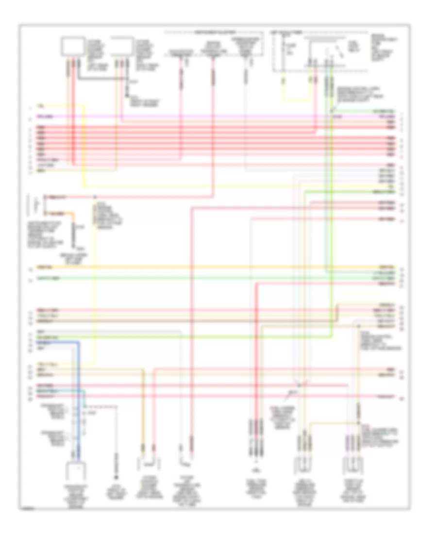
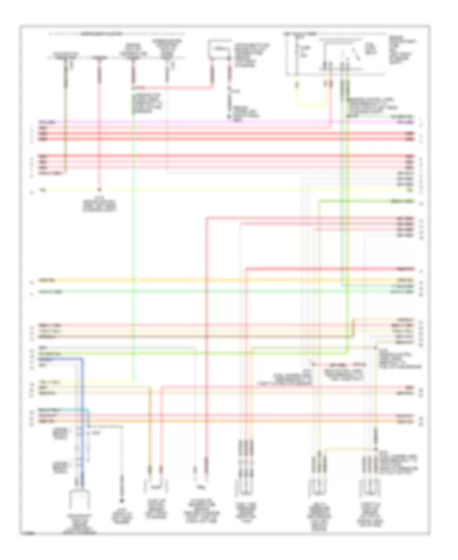
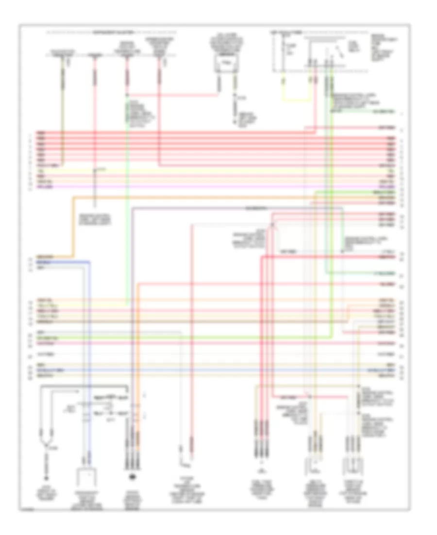
4.2L, Engine Performance Wiring Diagrams (1 of 4) for Ford Econoline E150 1998

List of elements for 4.2L, Engine Performance Wiring Diagrams (1 of 4) for Ford Econoline E150 1998:
- (behind upper left side of dash) g202
- (ends in harness)
- (eng ctrl harn, near breakout to fuel octane sensor)
- (front of right front fender)
- A/c on sig
- Air conditioning system
- Air ctrl sens
- Ckp sensor (+)
- Ckp sensor (-)
- Data link (+)
- Data link (-)
- Data link connector (partial) (left side of dash)
- Digital transmission range sensor (dtr sensor) (left side of transmission)
- Dtr-tr1
- Dtr-tr2a
- Dtr-tr4
- Ect
- Engine compartment fuse box (left front of engine compt)
- Engine coolant temperature sensor (top left front of engine)
- Evr sol
- Feps (eprom)
- Fp sending unit
- Fuel pump mon
- Fuse 10a
- Fuse 30a
- Fuse 5a
- G101 (front of right front fender)
- Gnd
- Hot at all times
- Hot in run or start
- I/p fuse panel (below left side of dash)
- Iat
- Ign coil 1
- Ign coil 2
- Ignition coil (left front of engine)
- Imrc
- Imrp 1
- Imrp 2
- Instrument cluster system
- Maf
- Mil
- Nca
- Not used
- O/d off
- Overdrive cancel switch
- Pcm power diode
- Pcm power relay
- Powertrain control module (left rear of engine compt, near brake master cylinder)
- Pwr gnd
- R n
- Radio capacitor no1 (attached to ignition coil)
- Red
- Rr ho2s sig (12)
- S110
- S127
- S140
- S142 (eng ctrl harn, near breakout to maf sensor)
- S147
- S268
- Shift sol 1
- Shift sol 2
- Spark plugs
- Tcs
- Tft
- To dtr sensor (diagram 4 of 4)
- Transmission control indicator lamp
- Vss (-)
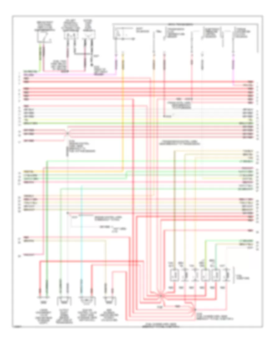
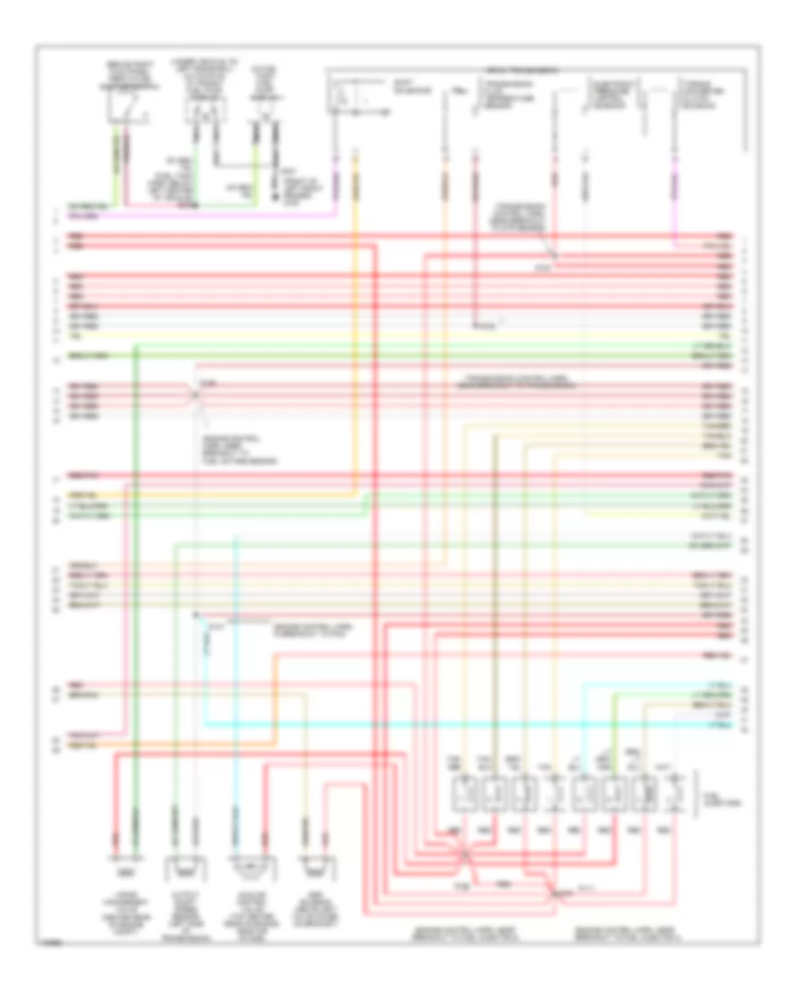
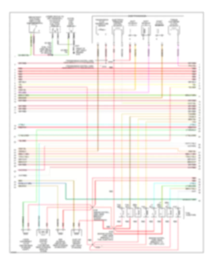
4.2L, Engine Performance Wiring Diagrams (2 of 4) for Ford Econoline E150 1998
List of elements for 4.2L, Engine Performance Wiring Diagrams (2 of 4) for Ford Econoline E150 1998:
- (behind upper left side of dash)
- (engine control harn, near breakout to 76-pin conn in left rear of engine compt)
- (fuel charge harn, near breakout to throttle position sensor)
- (speedometer/ odometer) vehicle speed input
- C224
- C225
- Crankshaft position sensor (lower right front of engine)
- Crankshaft position sensor shield
- Delta pressure feedback egr sensor (top right front of engine)
- Engine compartment fuse box (left front of engine compt)
- Engine coolant temperature gauge
- Fuel pump relay
- Fuel tank pressure sensor (near fuel tank)
- Fuse 30a
- G100 (front of left front fender)
- G101 (front of right front fender)
- G202
- Hot at all times
- Instrument cluster
- Instrumentation engine coolant temperature sensor (top front of engine, on heater outlet elbow)
- Intake air temperature sensor (center of engine compt, part of clean air tube)
- Intake manifold runner control (right rear top of engine)
- Intake manifold runner position sensor no1 (left rear of intake)
- Intake manifold runner position sensor no2 (right rear of intake)
- Malfunction indicator
- Nca
- Red
- Red/pnk
- S103
- S104 (fuel charge harn, near breakout to 16-pin conn near a/c pressure cut-out switch)
- S107
- S126
- S133 (engine control harn, near breakout to fuel octane sensor)
- S138 (engine control harn, near breakout to fuel octane sensor)
- S167
- Throttle position sensor (on top of engine, near air intake)
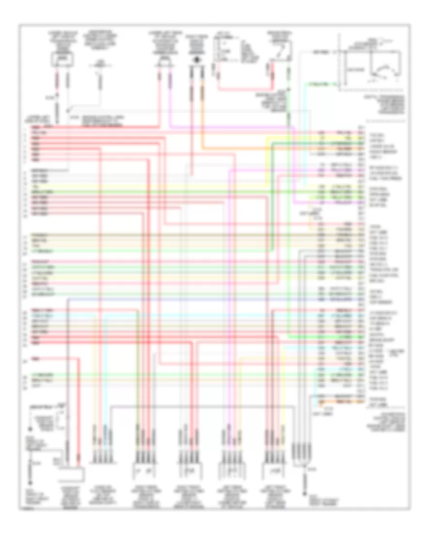
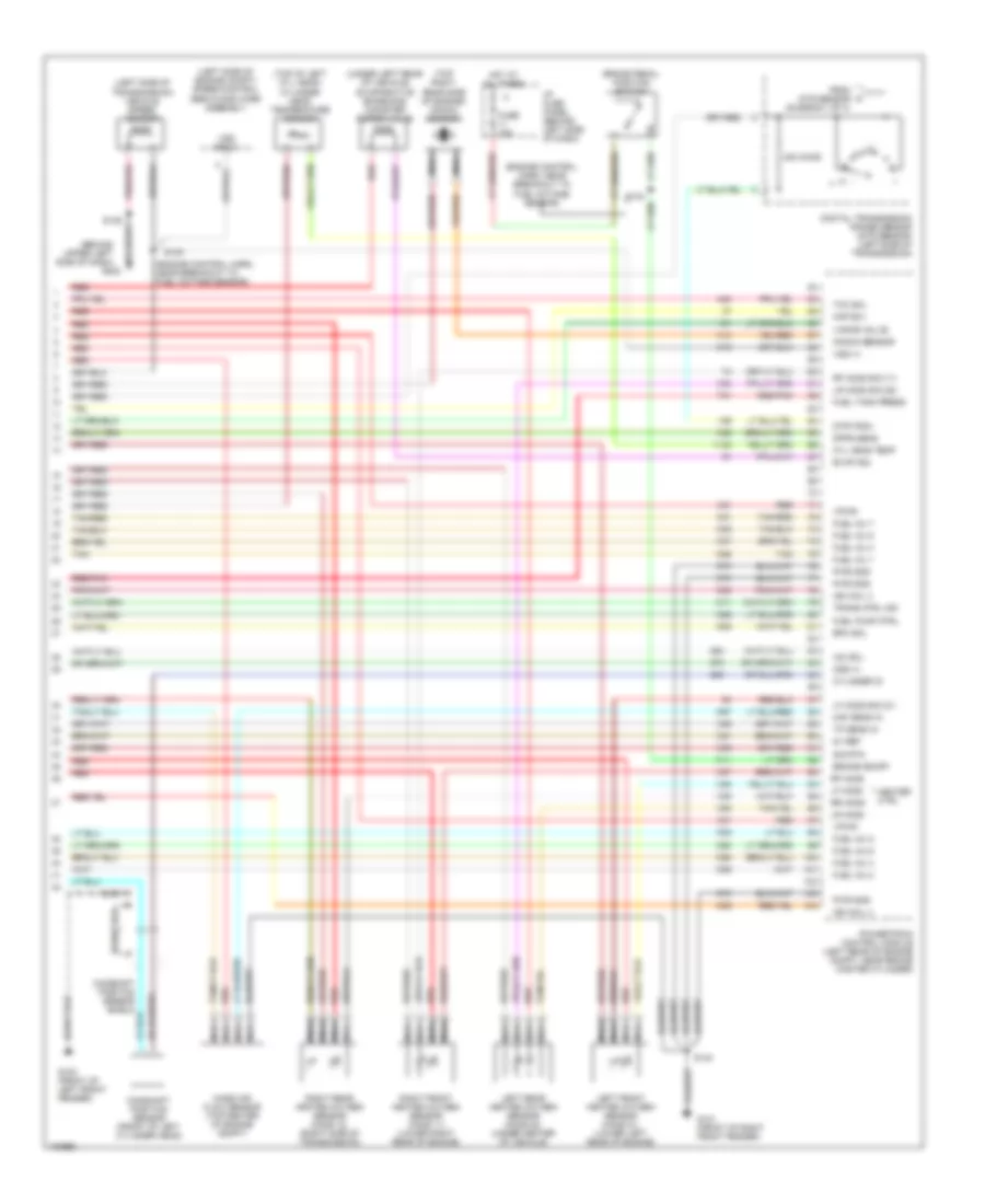
4.2L, Engine Performance Wiring Diagrams (3 of 4) for Ford Econoline E150 1998
List of elements for 4.2L, Engine Performance Wiring Diagrams (3 of 4) for Ford Econoline E150 1998:
- (behind right kick panel) inertia fuel shut-off switch
- (center rear of engine compt)
- (engine control harn, in breakout to pcm)
- (fuel charge harn, near breakout to fuel injector 2)
- (fuel tank harn, below left center of vehicle) s309
- (in fuel tank) fuel pump module
- (not used)
- (on left frame rail) (cutaways) in transit fuel pump module
- (trans cntrl harn, near breakout to dtr sensor)
- (transmission control harn, near breakout to transmission)
- 4r70w transmission
- C116
- Egr solenoid (above center of right valve cover)
- Electronic pressure control solenoid
- Fuel injectors
- G100 (front of left front fender)
- Idle air control valve (right side of engine, near ignition coil)
- Nca
- Output shaft speed sensor (left side of transmission)
- Red
- Red/pnk
- S100
- S102
- S105 (fuel charge harn, near breakout to fuel injector 3)
- S106
- S136 (engine control harn, near breakout to fuel octane sensor)
- S137
- S307
- Shift solenoids
- Tan
- Torque converter clutch solenoid
- Transmission fluid temperature sensor
- Vapor management valve
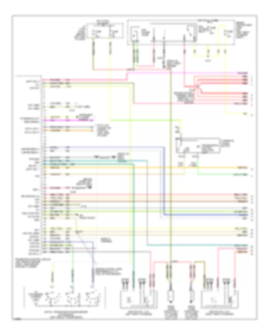
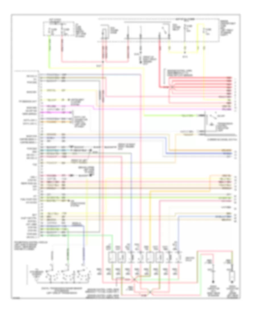
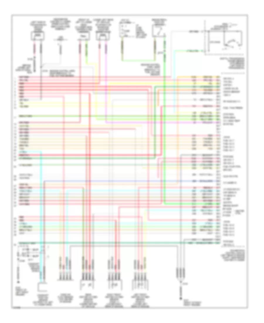
4.2L, Engine Performance Wiring Diagrams (4 of 4) for Ford Econoline E150 1998
List of elements for 4.2L, Engine Performance Wiring Diagrams (4 of 4) for Ford Econoline E150 1998:
- (engine control harn, near breakout to fuel octane sensor)
- (near brake master cylinder) speed control servo/amplifier assembly
- (not used)
- (right rear side of engine) knock sensor
- (under left rear of vehicle) evaporative emissions canister purge valve
- (under vehicle, left side of transmission) vehicle speed sensor
- (upper left side of dash)
- 240 ohms
- 5v ref
- Brake on/off
- Brake pedal position switch
- C116
- Camshaft position sensor (on front center of engine)
- Camshaft position sensor shield
- Cmp sensor
- Digital transmission range sensor (dtr sensor) (left side of transmission)
- Dpfe sens
- Dtr-tr3a
- Epc sol
- Evap sol
- From dtr sensor (diagram 1 of 4)
- Fuel inj 1
- Fuel inj 2
- Fuel inj 3
- Fuel inj 4
- Fuel inj 5
- Fuel inj 6
- Fuel pump ctrl
- Fuel tank press
- Fuse 15a
- G100 (front of left front fender)
- G101 (front of right front fender)
- G202
- Heater ctrl
- Hot at all times
- I/p fuse panel (below left side of dash)
- Iac sol
- Ign coil 3
- Kap b(+)
- Knock sensor
- Left front heated oxygen sensor (ho2s 21) (left rear of engine)
- Left rear heated oxygen sensor (ho2s 22) (under center of vehicle)
- Lf ho2s
- Lf ho2s sig (21)
- Lr ho2s
- Lr ho2s sig (22)
- Maf sens in
- Mass air flow sensor (on top (center of engine compt)
- Nca
- Not used
- Oss (+)
- Powertrain control module (left rear of engine compt, near master cylinder)
- Pwr gnd
- Red
- Red/pnk
- Rf ho2s
- Rf ho2s sig (11)
- Right front heated oxygen sensor (ho2s 11) (lower right rear of engine)
- Right rear heated oxygen sensor (ho2s 12) (right side of transmission)
- Rr ho2s
- S135
- S139
- S140
- S167
- Sig rtn
- Tan
- Tan/red
- Tcc sol
- Tp sens in
- Trans ctrl ind
- Vapor valve
- Vpwr
- Vss (+)
- Vss input
4.6L
4.6L, Engine Performance Wiring Diagrams (1 of 4) for Ford Econoline E150 1998
List of elements for 4.6L, Engine Performance Wiring Diagrams (1 of 4) for Ford Econoline E150 1998:
- (behind upper left side of dash) g202
- (ends in harness)
- (engine control harn, near breakout to fuel octane sensor)
- (engine control harness, near breakout to mass airflow sensor)
- (front of right front fender)
- (front of right front fender) g101
- (not used)
- A/c on sig
- Air conditioning
- Air ctrl sens
- C116
- Data link (+)
- Data link (-)
- Data link connector (partial) (left side of dash)
- Digital transmission range sensor (dtr sensor) (left side of transmission)
- Dtr-tr1
- Dtr-tr2
- Dtr-tr4
- Ect
- Engine compartment fuse box (left front of engine compt)
- Evr sol
- Feps (eprom)
- Fp sending unit
- Fuel pump mon
- Fuse 10a
- Fuse 30a
- Fuse 5a
- Gnd
- Hot at all times
- Hot in run or start
- I/p fuse panel (behind left side of dash)
- Iat
- Ign coil 1
- Ign coil 2
- Ignition coil 1 & 2 (left front of engine)
- Ignition coil 3 & 4 (right front of engine)
- Imrc
- Instrument cluster system
- Maf
- Mil
- Misfire sens (+)
- Misfire sens (-)
- Nca
- Not used
- O/d off
- Overdrive cancel switch
- Pcm power diode
- Pcm power relay
- Powertrain control module (left rear of engine compt, near brake master cylinder)
- Pwr gnd
- R n
- Radio noise capacitor 1 (attached to ignition coil 1 & 2)
- Radio noise capacitor 2 (attached to ignition coil 3 & 4)
- Red
- Rr ho2s sig (12)
- S110
- S127
- S139
- S140
- S142
- S147
- S150
- Shift sol 1
- Shift sol 2
- Spark plugs
- Tcs
- Tft
- To dtr sensor (diagram 4 of 4)
- Transmission control indicator lamp
- Vss (-)
4.6L, Engine Performance Wiring Diagrams (2 of 4) for Ford Econoline E150 1998
List of elements for 4.6L, Engine Performance Wiring Diagrams (2 of 4) for Ford Econoline E150 1998:
- (behind (upper left side of dash) g202
- (eng control harn, near breakout to fuel injector 7)
- (engine control harn, near breakout to 76-pin conn in left rear of engine compt) s126
- (speedometer/ odometer) vehicle speed input
- Crankshaft position sensor (lower right front of engine)
- Delta pressure feedback egr sensor (top left rear of engine)
- Engine compartment fuse box (left front of engine compt)
- Engine coolant temperature gauge
- Fuel pump relay
- Fuel tank pressure sensor (near fuel tank)
- Fuse 30a
- G100 (front of left front fender)
- Harn, near breakout to fuel octane sensor)
- Hot at all times
- Inlet air control sensor (left front of engine)
- Instrument cluster
- Instrumentation engine coolant temperature sensor (top front of engine)
- Intake air temperature sensor (center of engine compt, part of clean air tube)
- Malfunction indicator
- Misfire sensor shield
- Nca
- Power
- Red
- Red/pnk
- S103 (fuel charge harn, near breakout to throttle position sensor)
- S104 (fuel charge harn, near breakout to 16-pin conn near a/c pressure cut-out switch)
- S133
- S138 (engine control harn, near breakout to fuel octane sensor)
- S154
- S167
- S175 (engine control harn, left rear of engine compt)
- Throttle position sensor (on top of engine, near air intake)
4.6L, Engine Performance Wiring Diagrams (3 of 4) for Ford Econoline E150 1998
List of elements for 4.6L, Engine Performance Wiring Diagrams (3 of 4) for Ford Econoline E150 1998:
- (behind right kick panel) inertia fuel shut-off switch
- (center rear of engine compt)
- (engine control harn, in breakout to pcm)
- (engine control harn, near breakout to fuel injector 4)
- (engine control harn, near breakout to fuel injector 8)
- (engine control harn, near breakout to fuel octane sensor)
- (front of left front fender) g100
- (fuel tank harn, below left center of vehicle) s309
- (in fuel tank) fuel pump module
- (transmission control harn, near breakout to dtr sensor)
- (transmission control harn, near breakout to transmission)
- (under vehicle, on left frame rail) (cutaways) in transit fuel pump module
- 4r70w transmission
- Egr solenoid (above left valve cover, on bracket)
- Electronic pressure control solenoid
- Fuel injectors
- Idle air control valve (top center rear of engine, near air intake)
- Nca
- Output shaft speed sensor (left side of transmission)
- Red
- Red/pnk
- S100
- S102
- S136
- S137
- S151
- S152
- S307
- Shift solenoids
- Tan
- Tan/ red
- Tan/red
- Torque converter clutch solenoid
- Transmission fluid temperature sensor
- Vapor management valve
4.6L, Engine Performance Wiring Diagrams (4 of 4) for Ford Econoline E150 1998
List of elements for 4.6L, Engine Performance Wiring Diagrams (4 of 4) for Ford Econoline E150 1998:
- (behind upper left side of dash)
- (engine control harn, near breakout to fuel octane sensor)
- (left side of engine compt) speed control servo/amplifier assembly
- (left side of transmission) vehicle speed sensor
- (top of left cyl head) cylinder head temperature sensor
- (top right rear side of engine) knock sensor
- (under left rear of vehicle) evaporative emissions canister purge valve
- 240 ohms
- 5v ref
- Brake on/off
- Brake pedal position switch
- Camshaft position sensor (front of left cylinder head)
- Camshaft position sensor shield
- Cyl head temp
- Cylinder id
- Digital transmission range sensor (dtr sensor) (left side of transmission)
- Dpfe sens
- Dtr-tr3a
- Epc sol
- Evap sol
- From dtr sensor (diagram 1 of 4)
- Fuel inj 1
- Fuel inj 2
- Fuel inj 3
- Fuel inj 4
- Fuel inj 5
- Fuel inj 6
- Fuel inj 7
- Fuel inj 8
- Fuel pump ctrl
- Fuel tank press
- Fuse 15a
- G100 (front of left front fender)
- G101 (front of right front fender)
- G202
- Heater ctrl
- Hot at all times
- I/p fuse panel (behind left side of dash)
- Iac sol
- Ign coil 3
- Ign coil 4
- Kap b(+)
- Knock sensor
- Left front heated oxygen sensor (ho2s 21) (lower left rear of engine)
- Left rear heated oxygen sensor (ho2s 22) (under center of vehicle)
- Lf ho2s
- Lf ho2s sig (21)
- Lr ho2s
- Lr ho2s sig (22)
- Maf sens in
- Mass air flow sensor (top center of engine compt)
- Nca
- Oss (+)
- Powertrain control module (left rear of engine compt, near brake master cylinder)
- Pwr gnd
- Red
- Red/pnk
- Rf ho2s
- Rf ho2s sig (11)
- Right front heated oxygen sensor (ho2s 11) (lower right rear of engine)
- Right rear heated oxygen sensor (ho2s 12) (right side of transmission)
- Rr ho2s
- S135
- S139
- S140
- S167
- Sig rtn
- Tan
- Tan/red
- Tcc sol
- Tp sens in
- Trans ctrl ind
- Vapor valve
- Vpwr
- Vss (+)
- Vss input
5.4L
5.4L, Engine Performance Wiring Diagrams (1 of 4) for Ford Econoline E150 1998
List of elements for 5.4L, Engine Performance Wiring Diagrams (1 of 4) for Ford Econoline E150 1998:
- (behind upper left side of dash) g202
- (ends in harness)
- (engine control harn, near breakout to coil per plug 6)
- (engine control harn, near breakout to fuel injector 1)
- (engine control harn, near breakout to mass air flow sensor)
- (front of left front fender)
- (front of right front fender) g101
- A/c on sig
- Air conditioning system
- Data link (+)
- Data link (-)
- Data link connector (partial) (left side of dash)
- Digital transmission range sensor (dtr sensor) (left side of transmission)
- Dtr-tr1
- Dtr-tr2
- Dtr-tr4
- E4od ccs
- E4od ss1
- E4od ss2
- Ect
- Engine compartment fuse box (left front of engine compt)
- Evr sol
- Feps (eprom)
- Fp sending unit
- Fuel pump mon
- Fuse 10a
- Fuse 30a
- Fuse 5a
- G100
- Gnd
- Hot at all times
- Hot in run or start
- I/p fuse panel (behind left side of dash)
- Iat
- Ign coil 1
- Ign coil 3
- Ign coil 5
- Ign coil 6
- Ignition coils
- Inlet air ctrl
- Instrument cluster system
- Maf
- Mil
- Misfire sens (+)
- Misfire sens (-)
- Nca
- Not used
- O/d off
- Od off ind
- Overdrive cancel switch
- Pcm power diode
- Pcm power relay
- Powertrain control module (left side of engine compt, near brake master cylinder)
- Pwr gnd
- R n
- Radio capacitor no 1 (upper left rear of engine
- Radio capacitor no 2 (right rear of engine)
- Rear ho2s (22)
- Red
- S110
- S127
- S140
- S142
- S156
- S161
- S169
- S181
- S268
- Tcs
- Tft
- To dtr sensor (diagram 4 of 4)
- Transmission control indicator lamp
- Vss (-)
5.4L, Engine Performance Wiring Diagrams (2 of 4) for Ford Econoline E150 1998
List of elements for 5.4L, Engine Performance Wiring Diagrams (2 of 4) for Ford Econoline E150 1998:
- (behind left side of dash) g202
- (engine control harn, left rear of engine compt)
- (engine control harn, near breakout to 76-pin conn in left rear of engine compt) s126
- (engine control harn, near breakout to pcm) s137
- (on lower intake manifold) instrumentation engine coolant temperature sensor
- (speedometer/ odometer) vehicle speed input
- C224
- C225
- Crankshaft position sensor (lower center front of engine)
- Delta pressure feedback egr sensor (top right side of engine)
- Engine compartment fuse box (left front of engine compt)
- Engine coolant temperature gauge
- Fuel pump relay
- Fuel tank pressure transducer (near fuel tank)
- Fuse 30a
- G100 (front of left front fender)
- Hot at all times
- Instrument cluster
- Intake air temperature sensor (center of engine compt, part of clean air tube)
- Knock sensor (top right rear of engine)
- Malfunction indicator
- Nca
- Power
- Red
- Red/pnk
- S136 (engine control harn, near breakout to a/c cutout switch)
- S138 (engine control harn, near breakout to a/c cutout switch)
- S139
- S157 (engine control harn, near breakout to coil per plug 9)
- S158 (engine control harn, near breakout to radio noise capacitor 1)
- S169
- S170
- S171
- S175
- Throttle position sensor (top of engine, near air intake)
5.4L, Engine Performance Wiring Diagrams (3 of 4) for Ford Econoline E150 1998
List of elements for 5.4L, Engine Performance Wiring Diagrams (3 of 4) for Ford Econoline E150 1998:
- (behind right kick panel) inertia fuel shut-off switch
- (center rear of engine compt)
- (engine control harn, near breakout to coil per plug 2)
- (front of left front fender) g100
- (fuel tank harn, below left center of vehicle) s309
- (in fuel tank) fuel pump module
- (left front of engine)
- (transmission control harn, near breakout to dtr sensor)
- (transmission control harn, near breakout to transmission)
- (under vehicle, on left frame rail) (cutaways) in transit fuel pump module
- Coast clutch solenoid
- E4od transmission
- Egr solenoid (above left rear of engine, on bracket)
- Electronic pressure control solenoid
- Fuel injectors
- Idle air control valve (top center rear of engine, near air intake)
- Inlet air control sensor
- Nca
- Red
- Red/pnk
- S100
- S102
- S155 (engine control harn, near breakout to fuel injector 6)
- S159 (engine control, harn, near breakout to e4od transmission)
- S160
- S307
- Shift solenoid
- Tan
- Tan/ red
- Tan/red
- Torque converter clutch solenoid
- Transmission fluid temperature sensor
- Vapor management valve
5.4L, Engine Performance Wiring Diagrams (4 of 4) for Ford Econoline E150 1998
List of elements for 5.4L, Engine Performance Wiring Diagrams (4 of 4) for Ford Econoline E150 1998:
- (behind upper left side of dash)
- (engine control harn, near breakout to fuel octane sensor)
- (front of left cylinder head) cylinder head temperature sensor
- (left side of transmission) vehicle speed sensor
- (near brake master cylinder) speed control servo/amplifier assembly
- (under left rear of vehicle) evaporative emissions canister purge valve
- 270 ohms
- 5v ref
- Brake on/off
- Brake pedal position switch
- Camshaft position sensor (on front of left cylinder head)
- Camshaft position sensor shield
- Cyl head temp
- Cylinder id
- Digital transmission range sensor (dtr sensor) (left side of transmission)
- Dpfe sens
- Dtr-tr3a
- Epc sol
- Evap sol
- From dtr sensor (diagram 1 of 4)
- Fuel inj 1
- Fuel inj 2
- Fuel inj 3
- Fuel inj 4
- Fuel inj 5
- Fuel inj 6
- Fuel inj 7
- Fuel inj 8
- Fuel pump ctrl
- Fuel tank press
- Fuse 15a
- G100 (front of left front fender)
- G101 (front of right front fender)
- G202
- Heater ctrl
- Hot at all times
- I/p fuse panel (behind left side of dash)
- Idle air ctrl
- Ign coil 2
- Ign coil 4
- Ign coil 7
- Ign coil 8
- Kap b(+)
- Knock sensor
- Left front heated oxygen sensor (ho2s 21) (lower left rear of engine)
- Lf ho2s
- Lf ho2s sig (21)
- Maf sens in
- Mass air flow sensor (top center of engine)
- Nca
- Powertrain control module (left rear of engine compt, near brake master cylinder)
- Pwr gnd
- R ho2s
- Rear heated oxygen sensor (ho2s 22) (under center of vehicle)
- Red
- Red/pnk
- Rf ho2s
- Rf ho2s sig (11)
- Right front heated oxygen sensor (ho2s 11) (lower right rear of engine)
- S135
- S139
- S140
- S169
- S170
- S171
- Sig rtn
- Tan
- Tan/red
- Tcc sol
- Tp sens in
- Vapor valve
- Vpwr
- Vss (+)
- Vss input