
SHIFT INTERLOCKS
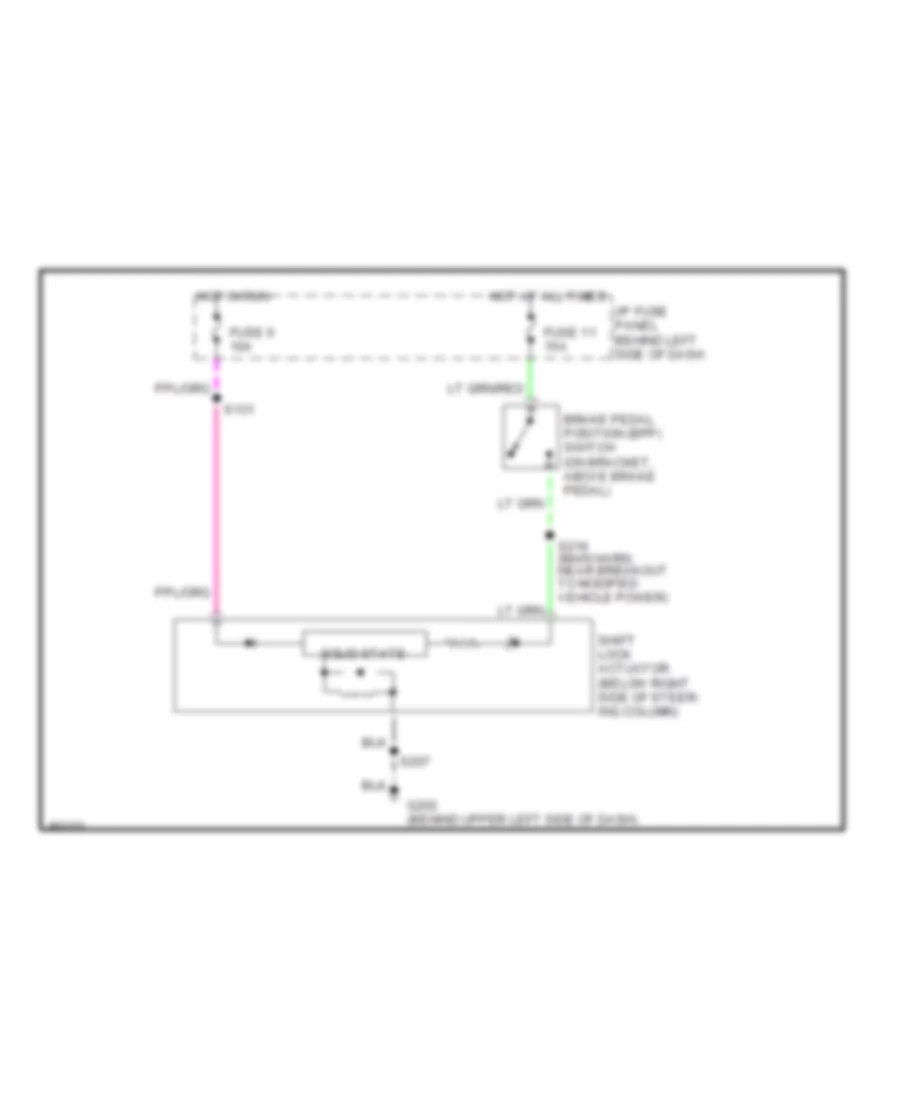
Shift Interlock Wiring Diagram for Ford Econoline E150 1998
List of elements for Shift Interlock Wiring Diagram for Ford Econoline E150 1998:
AIR CONDITIONINGCOMPUTER DATA LINESCRUISE CONTROLANTI-LOCK BRAKESEXTERIOR LIGHTSINTERIOR LIGHTSHEADLIGHTSENGINE PERFORMANCEGROUND DISTRIBUTIONPOWER DISTRIBUTIONPOWER DOOR LOCKSINSTRUMENT CLUSTERPOWER MIRRORSHORNPOWER SEATSRADIOSUPPLEMENTAL RESTRAINTSPOWER WINDOWSTRANSMISSIONWARNING SYSTEMSSHIFT INTERLOCKSSTARTING/CHARGINGWIPER/WASHER